RB-SiC base reflector surface modified layer structure and preparation method thereof

A technology of surface modification layer and substrate surface, applied in coating, sputtering coating, metal material coating process, etc. Problems such as poor polishing characteristics of the sexual layer

Inactive Publication Date: 2012-11-07
CHANGCHUN INST OF OPTICS FINE MECHANICS & PHYSICS CHINESE ACAD OF SCI
View PDF0 Cites 0 Cited by
  • Summary
  • Abstract
  • Description
  • Claims
  • Application Information

AI Technical Summary

Problems solved by technology

Research and practice have shown that the effect of directly using ion-assisted preparation of Si-modified layers to modify the surface of RB-SiC substrates is not very satisfactory. The reason is that the Si-modified layers grown on the two-phase composition of RB-SiC substrates uneven (such as image 3 As shown), the growth of the Si modified layer on the surface of the RB-SiC substrate has a preferred orientation, and the growth conditions on the SiC and Si two-phase components are obviously different, and its distribution replicates the situation on the original substrate surface
The difference in the nucleation density of the Si film growth in the two cases is large, which makes the physical properties of the Si film grown on the two-phase composition different, which directly leads to the difference in their polishing characteristics.
This will inevitably lead to poor polishing properties of the modified layer, which will affect the final modification effect.
[0005] Although the method of directly preparing the Si modified layer with ion-assisted modification is not good for the modification effect of the RB-SiC substrate mirror, but because the preparation cost of RB-SiC is low, it can achieve near-net size molding, and is very suitable for the preparation of complex Lightweight large-aperture mirror substrate, these comprehensive performance advantages determine its indispensable position in future aerospace applications

Method used


Image

  • RB-SiC base reflector surface modified layer structure and preparation method thereof
  • RB-SiC base reflector surface modified layer structure and preparation method thereof
  • RB-SiC base reflector surface modified layer structure and preparation method thereof

Examples


Embodiment 1

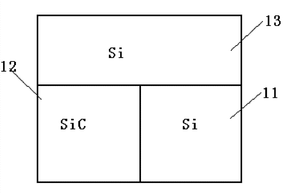
[0029] The preparation method of the RB-SiC base reflector structure of the present invention comprises the following specific steps:

[0030] 1. Preparation of coating conditions: fix the RB-SiC substrate on the workpiece fixture of the coating machine, and put Si grains in the crucible; vacuumize the vacuum chamber of the coating machine to 1.0×10 -3 Pa; bake in the temperature range of 200°C and keep the temperature constant for 30 minutes; then use the Kaufman ion source placed in the coating machine to fill the substrate with Ar gas for 20 minutes of ion cleaning, and the Ar gas volume flow rate is 25 sccm;

[0031] 2. Si phase composition on the surface of carbonized RB-SiC substrate: adjust the Kaufman ion source to reduce the volume flow rate of Ar gas to 8 sccm, and at the same time reduce the CH 4 Gas feed, CH 4 The gas volume flow rate is 15 sccm; adjust the Kaufman ion source so that the plate voltage reaches 600V, the beam current reaches 150mA, and the CH 4 Ion...

Embodiment 2

[0036] The preparation method of the RB-SiC base mirror structure of the present invention comprises the following specific steps:

[0037] 1. Preparation of coating conditions: fix the RB-SiC substrate on the workpiece fixture of the coating machine, and put Si grains in the crucible; vacuumize the vacuum chamber of the coating machine to 1.5×10 -3 Pa; bake in the temperature range of 200°C and keep the temperature constant for 50 minutes; then use the Kaufman ion source placed in the coating machine to fill the substrate with Ar gas for 40 minutes of ion cleaning, and the Ar gas volume flow rate is 25 sccm;

[0038] 2. Si phase composition on the surface of carbonized RB-SiC substrate: adjust the Kaufman ion source to reduce the volume flow rate of Ar gas to 11 sccm, and at the same time reduce the CH 4 Gas feed, CH 4 The gas volume flow rate is 15 sccm; adjust the Kaufman ion source so that the plate voltage reaches 700V, the beam current reaches 150mA, and the CH 4 Ioniz...

Embodiment 3

[0043] The preparation method of the RB-SiC base mirror structure of the present invention comprises the following specific steps:

[0044] 1. Preparation of coating conditions: fix the RB-SiC substrate on the workpiece fixture of the coating machine, and put Si grains in the crucible; vacuumize the vacuum chamber of the coating machine to 1.5×10 -3 Pa; bake in the temperature range of 300°C and keep the temperature constant for 40 minutes; then use the Kaufman ion source placed in the coating machine to fill the substrate with Ar gas for 30 minutes of ion cleaning, and the Ar gas volume flow rate is 30 sccm;

[0045] 2. Si phase composition on the surface of carbonized RB-SiC substrate: adjust the Kaufman ion source to reduce the volume flow rate of Ar gas to 10 sccm, and at the same time reduce the CH 4 Gas feed, CH 4 The gas volume flow rate is 20sccm; the Kaufman ion source is adjusted to make the plate voltage reach 700V, the beam current reaches 160mA, and the CH 4 Ion...


PUM

PropertyMeasurementUnit
thicknessaaaaaaaaaa
thicknessaaaaaaaaaa
surface roughnessaaaaaaaaaa

Abstract

The invention relates to an RB-SiC substrate reflector surface modified layer structure. The structure contains a SiC phase component, a diamond like carbon film buffer layer and a uniform and dense Si modified layer, wherein the SiC phase component is obtained by carbonizing the Si phase component on the surface of an RB-SiC substrate; the diamond like carbon film buffer layer is prepared on thesurfaces of the SiC phase component of the RB-SiC substrate and the SiC phase component prepared through the carbonization of the Si phase component; and the Si modified layer grows on the diamond like carbon film buffer layer. The preparation method adopts the ion implantation method and comprises the following steps: firstly, carbonizing the Si phase component on the surface of the RB-SiC substrate to the SiC component; secondly, growing the diamond like carbon film buffer layer on the SiC component; and finally, using the high energy ion supplementary means to grow the Si modified layer onthe diamond like carbon film buffer layer. The Si modified layer is dense and uniform, thus the polishing characteristic of the structure can be greatly improved, the optical quality of the surface of the polished substrate is greatly increased and the space utilization of the RB-SiC substrate reflector can be ensured.

Description

field of invention [0001] The invention belongs to the technical field of thin film deposition, and relates to a surface modification layer structure and a preparation method of an RB-SiC base reflector. Background technique [0002] With its excellent physical and mechanical properties, SiC material has become one of the preferred materials for the substrate of large-aperture mirrors used in space. However, it is difficult to obtain a high-quality optical surface for the directly polished SiC substrate mirror, and its surface optical scattering is still large, which cannot meet the application requirements of high-quality space optical systems, making it difficult for space optical systems to achieve ideal resolution. In order to solve this contradiction, it is necessary to modify the surface of the SiC base reflector to improve the optical quality of the surface to meet the urgent requirements of the space optical system for high resolution. [0003] The so-called surface...

Claims


Application Information

Patent Timeline
Patent Type & Authority Patents(China)
IPC IPC(8): C23C14/48C23C14/30C23C14/02C23C14/06C23C14/18G02B1/10
Inventor 申振峰高劲松
Owner CHANGCHUN INST OF OPTICS FINE MECHANICS & PHYSICS CHINESE ACAD OF SCI
Why Eureka
Try Eureka