
Pipe joint with functions of electricity defending wall

A pipe joint and anti-electric wall technology, which is applied in the field of pipe joints, can solve the problems that the two ends of the insulating water pipe are not directly connected together, cannot guarantee user safety, increase production costs, etc., and achieve simple structure, small size, and easy processing. convenient effect

Inactive Publication Date: 2011-06-15
许明德
View PDF28 Cites 0 Cited by
  • Summary
  • Abstract
  • Description
  • Claims
  • Application Information

AI Technical Summary

Problems solved by technology

[0010] Combining the above multiple patents, it can be found that there is a common problem: when calculating the length L of the insulating water pipe, most of them still take the value of the safe current (the maximum allowable leakage current) as 10mA (formally implemented on July 1, 2007 The national standard is 5mA), so the length L of the insulating water pipe is shortened by half, which cannot guarantee the safety of users; to ensure the safety of users, the length L of the insulating water pipe needs to be doubled, and the insulating water pipe must be longer
[0011] In addition, the above-mentioned multiple patents also have a common feature that the two ends of the insulating water pipe are not directly connected together.
The result of doing like this may cause several consequences: the one, there is a long insulating water pipe in the middle, so the overall length is relatively long, and the installation is inconvenient; the second is that the structure is too complicated because the overall length should be shortened; It is because the two ends of the joint are not directly connected together, and there is a long insulating water pipe in the middle. When one end of the joint is fixed, the other end of the joint needs to be fixed again to be firm, which increases the production cost.

Method used


Image

  • Pipe joint with functions of electricity defending wall
  • Pipe joint with functions of electricity defending wall
  • Pipe joint with functions of electricity defending wall

Examples


Embodiment Construction

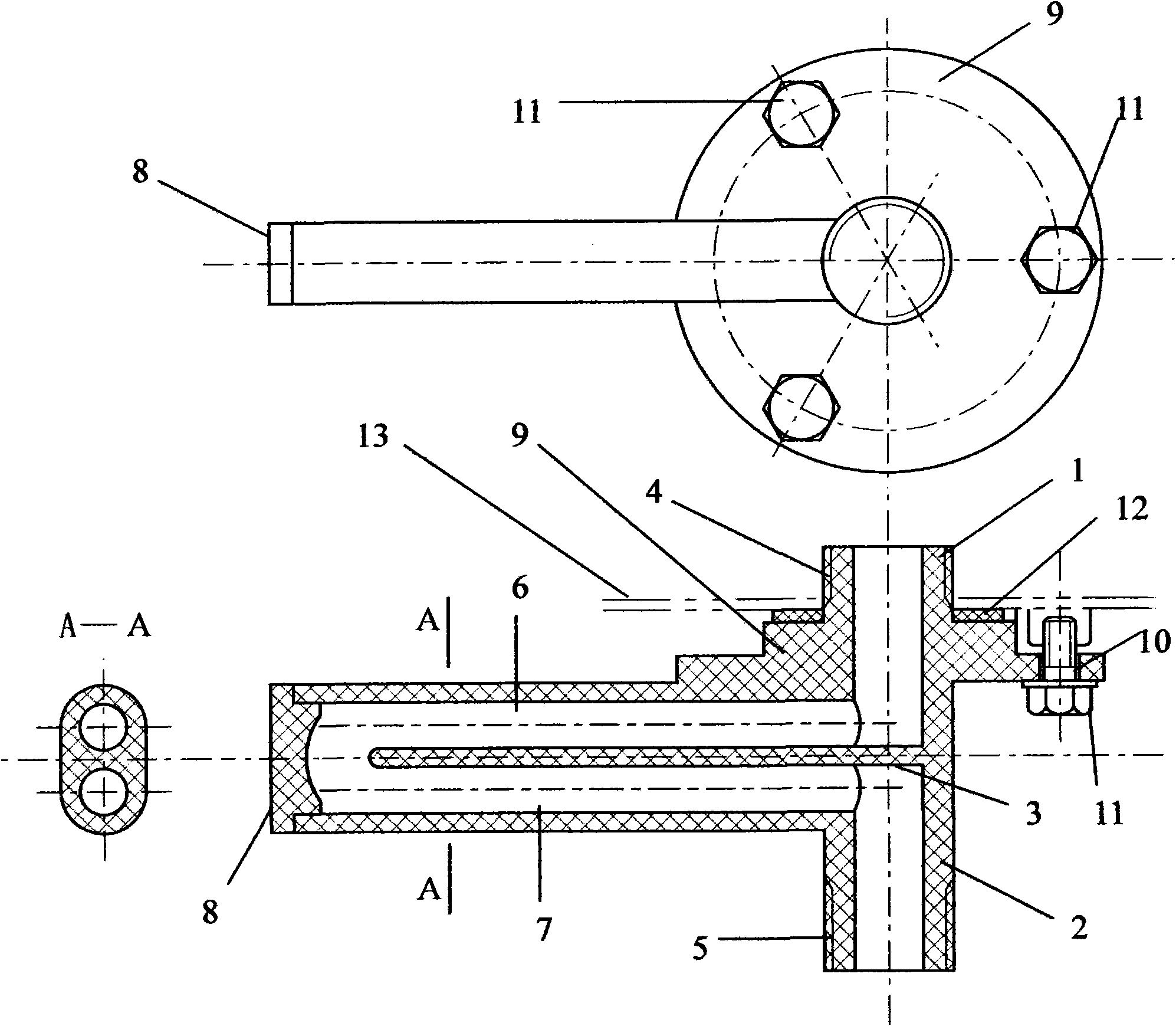
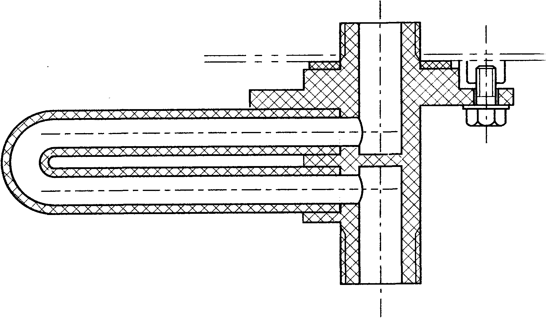
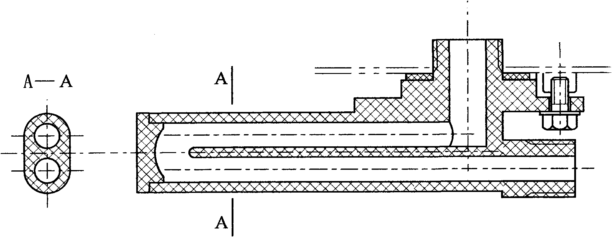
[0040] as attached figure 1 to attach Figure 9 As shown, the pipe joint with the function of the electric wall of the present invention, all its parts (except the bolt, which is made of metal material, which is an accessory of the pipe joint with the function of the electric wall) are all made of high insulation, high temperature resistance, water resistance It is made of decomposed and pressure-resistant plastic material.

[0041] as attached figure 1 As shown, the interface 1 and the interface 2 are directly connected, and the two are separated by a partition 3; the central axis of the interface 1 and the interface 2 is the same axis; there is a thread 4 on the interface 1, and a thread 5 on the interface 2; the U-shaped pipe is composed of The straight pipe 6, the straight pipe 7 and the bottom 8 are composed, and the inner cavity of the three is connected to form a U-shaped pipe; the interface 1 is connected to the straight pipe 6 and the inner cavity is connected, and ...


PUM


Abstract

The invention discloses a pipe joint with a functions of an electricity defending wall, which has the advantages of strong electricity resistance, safety and reliability, simple structure, convenience for machining, low maintenance rate and low cost. All parts of the pipe joint are made from high-insulation, high-temperature and hydrolysis resistant and pressureproof plastic materials; two ports of the pipe joint are directly jointed, partitioned by a clapboard and respectively communicated with a U-shaped pipe, the total length of an inner cavity of the U-shaped pipe is larger than the square (centimetre-gram-second unit system) of a 106-time inner bore radius, and the electric resistance of water after water is introduced can ensure that a leakage current is smaller than a safe current, thereby ensuring the safety of a human body. The two ports of the pipe joint are directly jointed, therefore, the length of the pipe joint is smaller and the pipe joint is easy to be fixed and is suitable for various water heaters and other liquid circulating equipment requiring electric leakage prevention; in addition, the pipe joint is suitable for reforming various traditional water heaters, and an effect of ensuring safety can be achieved by only serially connecting the pipe joint with the functions of the electricity defending wall, provided by the invention, to the traditional water inlet and outlet.

Description

technical field [0001] The invention relates to a pipe joint, in particular to a pipe joint with the function of an electric wall. Background technique [0002] Equipment such as electric water heaters and solar water heaters with alternating current auxiliary heating (including photothermal solar water heaters and photovoltaic solar water heaters) often endanger human safety due to electric leakage. There are two most commonly used leakage prevention methods: one is to use a leakage switch, and when the leakage current exceeds the specified value, the power supply can be automatically cut off to ensure the safety and reliability of the electric heater; the other is to install a leakage switch on related equipment. Automatic detection device, when the leakage current exceeds the specified index, it will automatically alarm and remind the user to turn off the power to ensure the safety of the user. However, these two protection methods may lead to the user's dependence on th...

Claims


Application Information

Patent Timeline
Patent Type & Authority Applications(China)
IPC IPC(8): F16L25/02
Inventor 许明德
Owner 许明德
Features
  • Generate Ideas
  • Intellectual Property
  • Life Sciences
  • Materials
  • Tech Scout
  • Unparalleled Data Quality
  • Higher Quality Content
  • 60% Fewer Hallucinations
Learn More