
High-voltage phase wireless verifying instrument

A technology of high-voltage electricity and high-voltage electric field, which is applied to the phase angle between voltage and current, instruments, and measurement of electrical variables. It can solve problems such as high risk, heavy workload, and high wiring insulation requirements, and achieve safe test operations. Reliable, easy-to-operate, easy-to-manufacture effects

Inactive Publication Date: 2011-06-15
武汉特试特科技有限公司
View PDF0 Cites 3 Cited by
  • Summary
  • Abstract
  • Description
  • Claims
  • Application Information

AI Technical Summary

Problems solved by technology

[0003] In the industry, there are usually two methods for collecting high-voltage electrical signals on high-voltage lines. One is to use wired methods to collect signals, that is, lift the signal acquisition device to the high-voltage transmission line through an insulating rod, and hang the hook of the signal acquisition device on the high-voltage transmission line. The collected high-voltage signal is transmitted to the measuring device through the wire. Because the signal acquisition device is in direct contact with the high-voltage wire, this method has the disadvantages of high risk, high requirements for wiring insulation between the high-voltage lead wire and the equipment, and a large workload; The other is to collect high-voltage electrical signals wirelessly. The traditional wireless method is to lift the sampler to the high-voltage transmission line with an insulating rod. The sampler is in contact with the high-voltage transmission line. The signal collected by the sampler is sent to the ground through radio transmission. The main control machine held by the operator above, this wireless collection method still needs to connect the sampling machine with the high-voltage line, and also needs to adopt the wireless communication method, which has the disadvantages of certain danger and inconvenient operation

Method used


Image

  • High-voltage phase wireless verifying instrument
  • High-voltage phase wireless verifying instrument
  • High-voltage phase wireless verifying instrument

Examples


Embodiment Construction

[0014] The specific embodiments of the present invention will be described in detail below in conjunction with the accompanying drawings.

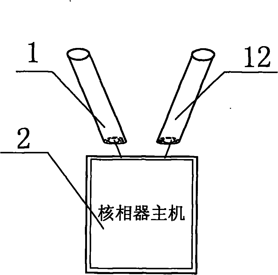
[0015] Such as figure 1 As shown, it is a schematic diagram of the high-voltage electric phase wireless verification instrument of the present invention. In this embodiment, the high-voltage electric phase wireless verification instrument host 2 and two non-contact high-voltage electric field sensors 1, the non-contact high-voltage electric field sensor 1 and the high-voltage electric field sensor 1 are included. The hosts 2 of the electrical phase wireless verification instrument are connected by signal lines, and the non-contact high-voltage electric field sensor 1 collects high-voltage signals and outputs them to the host 2 of the high-voltage electrical phase wireless verification instrument.

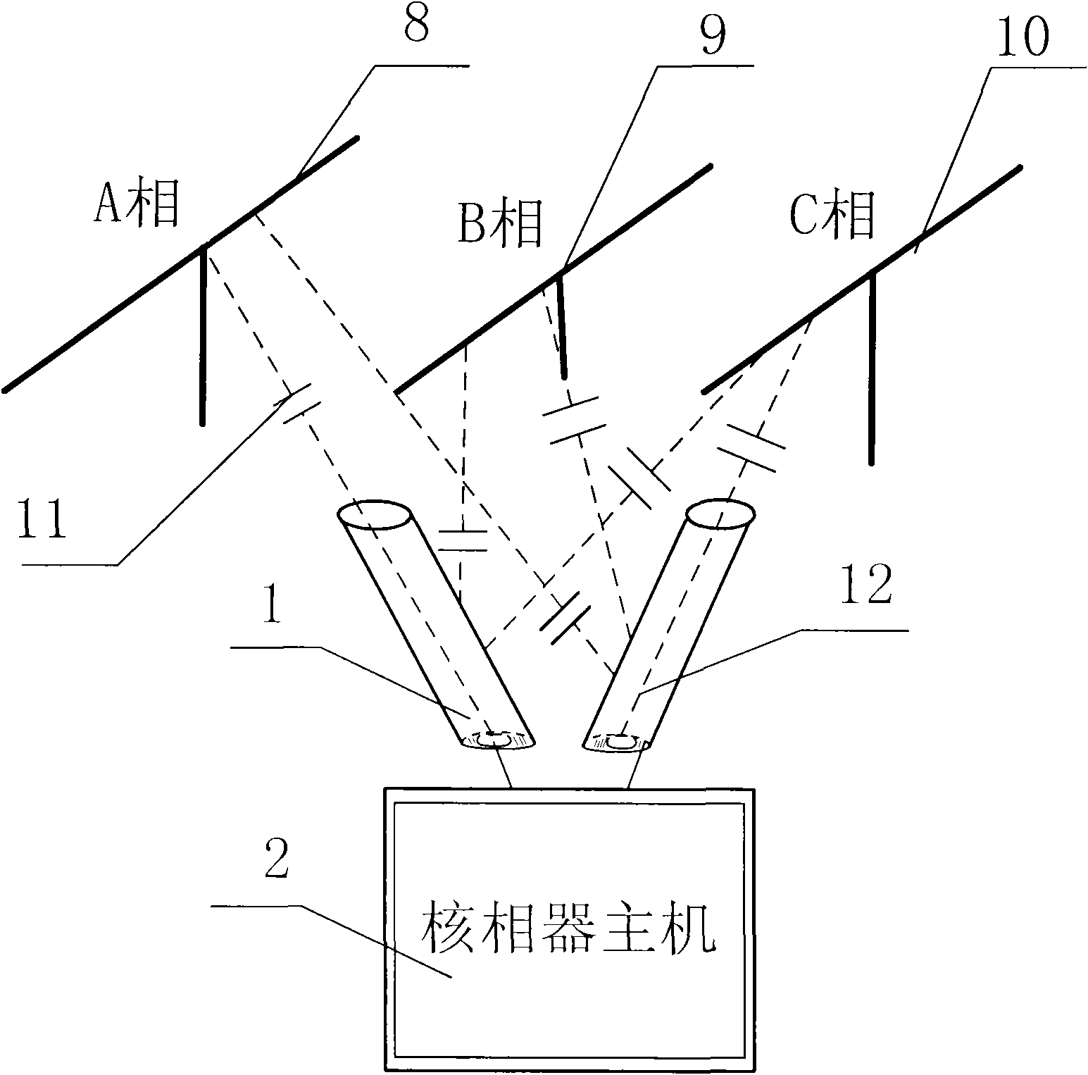
[0016] Such as image 3 Shown is a diagram showing the working state of the high-voltage electric phase wireless verification instrument of th...


PUM


Abstract

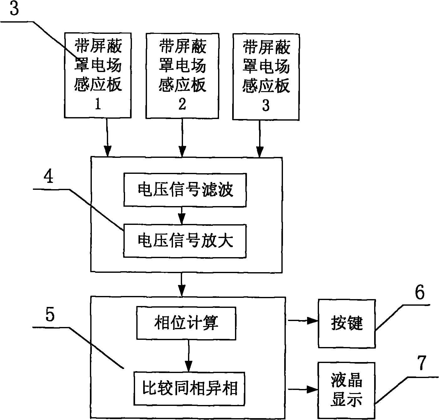
The invention relates to a high-voltage phase wireless verifying instrument. The instrument comprises at least two non-contact high-voltage electric field sensors and a verifying instrument host, wherein the verifying instrument host comprises a signal processing circuit module of which the output end is connected with the input end of a micro control unit (MCU) controlled calculation module; each non-contact high-voltage electric field sensor consists of an electric field induction plate and an electric field shielding cover which is covered outside the electric field induction plate and provided with an opening; and the signal output end of each non-contact high-voltage electric field sensor is connected with the signal input end of the high-voltage phase verifying instrument host. The high-voltage phase wireless verifying instrument has a simple structure and is safely and reliably operated and convenient to use; and the signal acquisition end of the high-voltage phase wireless verifying instrument is not required to be physically connected with a high-voltage power transmission line during testing.

Description

technical field [0001] The invention relates to a high-voltage transmission line phase sequence and phase detection verification device, in particular to a high-voltage electric phase wireless verification instrument. Background technique [0002] The long-distance transmission of high-voltage electricity at home and abroad usually adopts three-phase AC system. Before the new power plant is connected to the grid, before the new substation is put into operation, after the expansion and transformation of the power transmission and transformation project, and after the major transmission and transformation station equipment is overhauled, it is necessary to conduct a phase verification test before putting into operation, that is, it is necessary to check the two corresponding lines connected to the grid Whether in phase. Especially before the rebuilt transmission line is connected to the user's power transmission line, the voltage phase verification test of the three-phase hig...

Claims


Application Information

Patent Timeline
IPC IPC(8): G01R25/00
Inventor 汪泓
Owner 武汉特试特科技有限公司
Learn More