Cross section integrated laser vision fixed weight cutting method for continuously cast bloom and weight fixing device

A cutting method and continuous casting billet technology, applied in the field of metallurgy, can solve problems such as the problem of fixed weight that has not been well solved, the essential problem of not getting involved in fixed weight, and the theoretical accuracy is not thought about, so as to improve production efficiency and economic benefits, Simple structure and accurate calculation

Inactive Publication Date: 2011-06-22
HEBEI UNIVERSITY OF SCIENCE AND TECHNOLOGY
View PDF0 Cites 18 Cited by
  • Summary
  • Abstract
  • Description
  • Claims
  • Application Information

AI Technical Summary

Problems solved by technology

[0002]Continuous casting slabs should be cut at constant weight before entering the next rolling process. However, the problem of constant weight has not been well solved. Enterprises adopt fixed-length cutting system
This technology improves the accuracy of fixed weight to a certain extent, but it needs to add a weighing system on the basis of the existing fixed-length cutting system. It cannot be realized at all under certain circumstances; moreover, because it is not a fixed-weight cutting in the true sense, the effect is not very obvious
[0005] ② Some universities and research institutes at home and abroad have tried to apply laser vision technology to the fixed-weight cutting system of continuous casting slabs, but because they essentially use vision technology to improve the accuracy of length measurement, they have not been involved in the essential problem of fixed weight ( That is, how to improve the accuracy of measuring the cross-sectional area of ​​the continuous casting slab), so its effect is not obvious
Therefore, the patented device assumes that the cross-sectional area of ​​the continuous casting slab remains unchanged in a certain long section, and there will be errors in measuring the length, so its theoretical accuracy is still unthinkable, and it has great limitations.

Method used


Image

  • Cross section integrated laser vision fixed weight cutting method for continuously cast bloom and weight fixing device
  • Cross section integrated laser vision fixed weight cutting method for continuously cast bloom and weight fixing device
  • Cross section integrated laser vision fixed weight cutting method for continuously cast bloom and weight fixing device

Examples


Embodiment

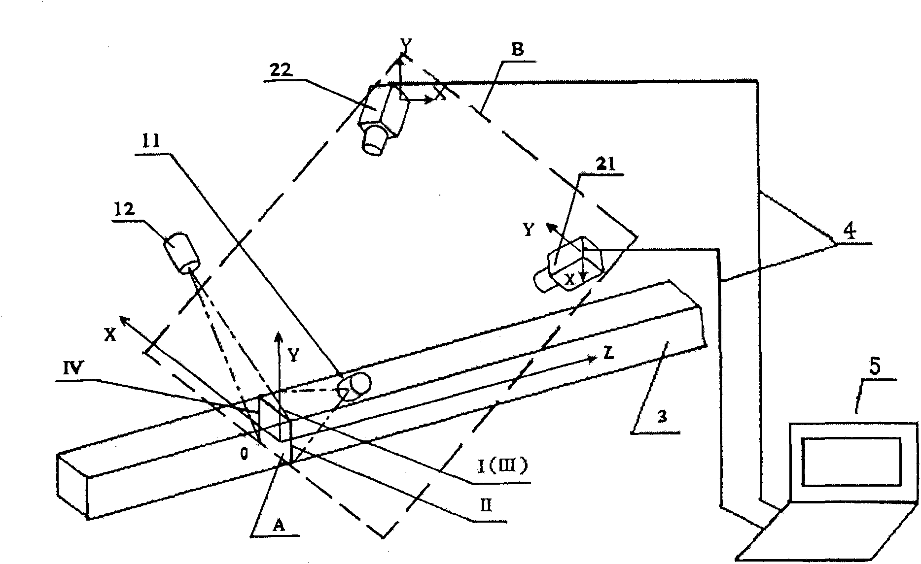
[0047] A cross-sectional integral type continuous casting slab laser vision fixed-weight cutting method, which is carried out according to the following steps:

[0048] ①Laser irradiation and CCD camera imaging

[0049] Using a linear laser to irradiate the laser on the cross-section of the continuous casting slab corresponding to the installation position of the cutting knife to form a light strip located in the same vertical plane A, the vertical plane A is perpendicular to the axis of the continuous casting slab;

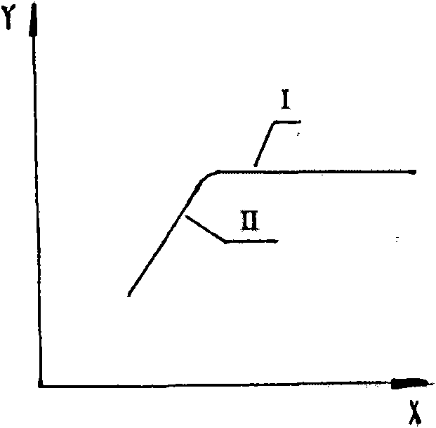
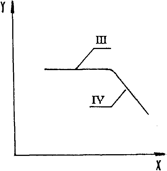
[0050] The rear part of the light strip is taken by a CCD camera to form a hologram of the light strip; the light strip curve fitting is performed to obtain the cross-sectional image of the position of the light strip on the continuous casting slab.

[0051] Laser irradiation and CCD camera imaging are carried out in the following steps:

[0052] (1) Installation and adjustment of linear laser

[0053] Installation: on the left and right sides of the continuous...


PUM


Abstract

The invention discloses a cross section integrated laser vision fixed weight cutting method for a continuously cast bloom and a weight fixing device. Real-time integration of the cross section outline area of the continuously cast bloom in the continuously cast bloom conveying speed direction is realized by using a laser device, a camera and a computer installed with image processing and weight fixing software through a synchronous technology of a visual imaging system and a cutting system so as to realize real-time high-precision calculation of the cross section outline area of the continuously cast bloom; the conventional fixed scale cutting system technology is upgraded into a fixed weight cutting system technology so as to greatly improve the fixed weight precision of the continuouslycast bloom, reduce the reject rate of subsequent steel products and improve the production efficiency and the economic benefit; and the weight fixing device has simple composition and accurate calculation. The method is applied in a steel or iron smelting process, and realizes fixed weight cutting of the continuously cast bloom.

Description

technical field [0001] The invention belongs to the field of metallurgy, and relates to a measurement method in the production process of steelmaking and continuous casting, in particular to a cross-sectional integral type continuous casting slab laser vision fixed-weight cutting method and a fixed-weight device. Background technique [0002] The continuous casting slab should be cut to fixed weight before entering the next rolling process, but because the fixed weight problem has not been well solved, most domestic iron and steel enterprises currently use the fixed-to-length cutting system. Restricted by factors such as mold wear, molten steel alloy composition and casting speed changes in the continuous casting process, the weight of the same length of slab cast in the same flow and at different time periods is not the same, and the difference is large, that is, the casting slab The cross-sectional area of ​​is constantly changing. This difference will directly affect the...

Claims


Application Information

Patent Timeline
Patent Type & Authority Applications(China)
IPC IPC(8): B22D11/126
Inventor 李保章黄凤山黄凤海黄永建
Owner HEBEI UNIVERSITY OF SCIENCE AND TECHNOLOGY
Why Eureka
Try Eureka