Method and system for monitoring current-carrying capacity of cable based on distributed optical fiber temperature measuring method

A distributed optical fiber and flow monitoring technology, applied in the direction of measuring electrical variables, measuring electricity, measuring devices, etc., can solve the problems of reduced operating life, cable overheating state, cumbersome calculation methods, etc., and achieve the effect of improving accuracy and reducing errors

Inactive Publication Date: 2011-06-22
STATE GRID SHANDONG ELECTRIC POWER
View PDF4 Cites 34 Cited by
  • Summary
  • Abstract
  • Description
  • Claims
  • Application Information

AI Technical Summary

Problems solved by technology

[0003] At present, the calculation of ampacity of cables adopts the internationally recognized IEC standard, but this standard can only meet the calculation of ampacity in simple scenarios and is not suitable for complex scenarios, which has certain limitations; on the other hand, the IEC standard provides The algorithm is suitable for manual calculation. This calculation method is too cumbersome. So far, the computerization of IEC is not yet mature and is still in the process of gradual development.
At the same time, the selection of parameters for current IEC ampacity

Method used


Image

  • Method and system for monitoring current-carrying capacity of cable based on distributed optical fiber temperature measuring method
  • Method and system for monitoring current-carrying capacity of cable based on distributed optical fiber temperature measuring method
  • Method and system for monitoring current-carrying capacity of cable based on distributed optical fiber temperature measuring method

Examples


Embodiment Construction

[0029] Below in conjunction with accompanying drawing and embodiment the present invention will be further described:

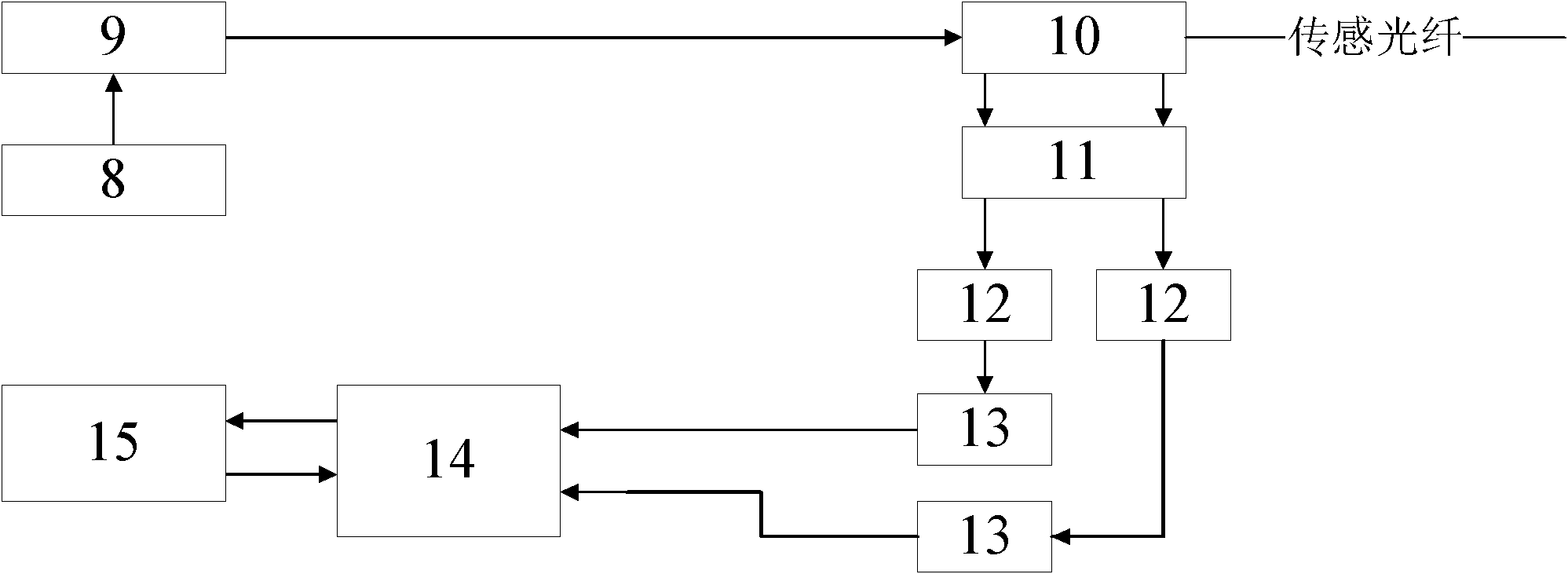
[0030] Such as figure 1 As shown, it is a distributed optical fiber temperature sensor system, which mainly includes sensing optical fiber, laser 9 and laser driver 8, bidirectional coupler 10, wavelength division multiplexer 11, photoelectric detector APD 12, amplifier 13, acquisition average accumulator 14 And microcomputer 15 forms. The pulsed light emitted by the laser 9 is used as the pumping light and injected into the sensing fiber through the coupler. When the pulsed light propagates forward in the sensing fiber, backscattered light is generated. Backscattered light filters out anti-Stokes light and Rayleigh light through optical filtering. Stokes scattering and anti-Stokes scattering are collectively referred to as Raman scattering, and then through photoelectric conversion and amplification circuits, the amplified signal is The high-speed data acq...


PUM


Abstract

The invention relates to a method and a system for monitoring current-carrying capacity of a cable based on a distributed optical fiber temperature measuring method. The system comprises a laser drive device which is matched with a temperature sensing device in a cable; the temperature sensing device is matched with the corresponding optical fiber splitter; the output end of each optical fiber splitter is connected with one end of the cable; the other end of the cable is connected with a wire distribution cabinet which is matched with demodulating equipment; and the output end of the demodulating equipment is connected with a cable integrated Ethernet chip (IEC) compute server which is output to a client terminal. Combining the distributed optical fiber temperature measuring method, by the method and system provided by the invention, the important parameters of the cable operation can be acquired; the stimulated accuracy is greatly improved through the comprehensive analysis of the current-carrying capacity, thus providing the decision standard for ensuring the safe operation of the city cables and the reasonable configuration of the transmission capacity.

Description

technical field [0001] The invention relates to a cable current-carrying capacity monitoring method and system based on a distributed optical fiber temperature measurement method. Background technique [0002] With the continuous development of industry and power system, the number of high-voltage cable lines in the power grid is increasing day by day, and the intensity of power transmission has been continuously increasing. The smart grid has put forward higher requirements for the power transmission system. , the core temperature reaches the allowable value. Once the cable is overloaded, the temperature of the wire core will rise sharply, which will accelerate the aging of the insulation and even cause thermal breakdown. Therefore, the operating temperature of the cable must be controlled, which requires the power operation department to reasonably dispatch the actual load of the cable. How to improve the power transmission capacity and power transmission efficiency of t...

Claims


Application Information

Patent Timeline
IPC IPC(8): G01R31/00G01R31/08G01K11/32G01K11/324
Inventor 陈静白万建王玉国张顺生宋来森彭红霞
Owner STATE GRID SHANDONG ELECTRIC POWER
Why Eureka
Try Eureka