Expandable and cuttable multi-shaft movement control system

A multi-axis motion and control system technology, applied in the field of numerical control, can solve the problems of limited maximum frequency, unfavorable system reliability and speed improvement, limited system performance and reliability, etc., to achieve good flexibility and adaptability, expansion and reduction. The effect of convenient and flexible applicability

Inactive Publication Date: 2011-06-29
GUANGZHOU LOKSHUN CNC EQUIP +1
View PDF0 Cites 18 Cited by
  • Summary
  • Abstract
  • Description
  • Claims
  • Application Information

AI Technical Summary

Problems solved by technology

[0005] (a) The main problem of the analog signal transmission form is that it is difficult to eliminate the influence of zero drift and temperature drift on the accuracy, and it is easy to be affected by external interference; the main problem of the pulse signal transmission form is that the motion control system and the servo drive system are connected by a non-coding method If the command pulse signal is directly transmitted, once the pulse is lost or the interference pulse is introduced, it is difficult to check and correct the error, and it is difficult to ensure the high reliability of information transmission; in addition, the pulse-driven servo drive system has a limited maximum frequency of receiving pulses.
Therefore, in traditional motion control, the transmission form of the above-mentioned servo drive signal seriously limits the improvement of system performance and reliability.
[0006] (b) Due to the servo drive with pulse signal or analog signal transmission, each control axis must perform digital/pulse or digital/analog conversion calculations. Therefore, each control axis of the motion control system needs to provide a set of complex interface circuits And programs, after the hardware of the motion co

Method used


Image

  • Expandable and cuttable multi-shaft movement control system
  • Expandable and cuttable multi-shaft movement control system
  • Expandable and cuttable multi-shaft movement control system

Examples


Embodiment

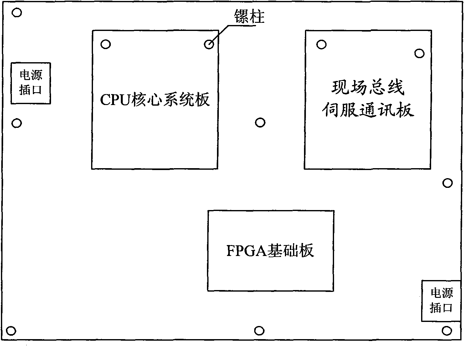
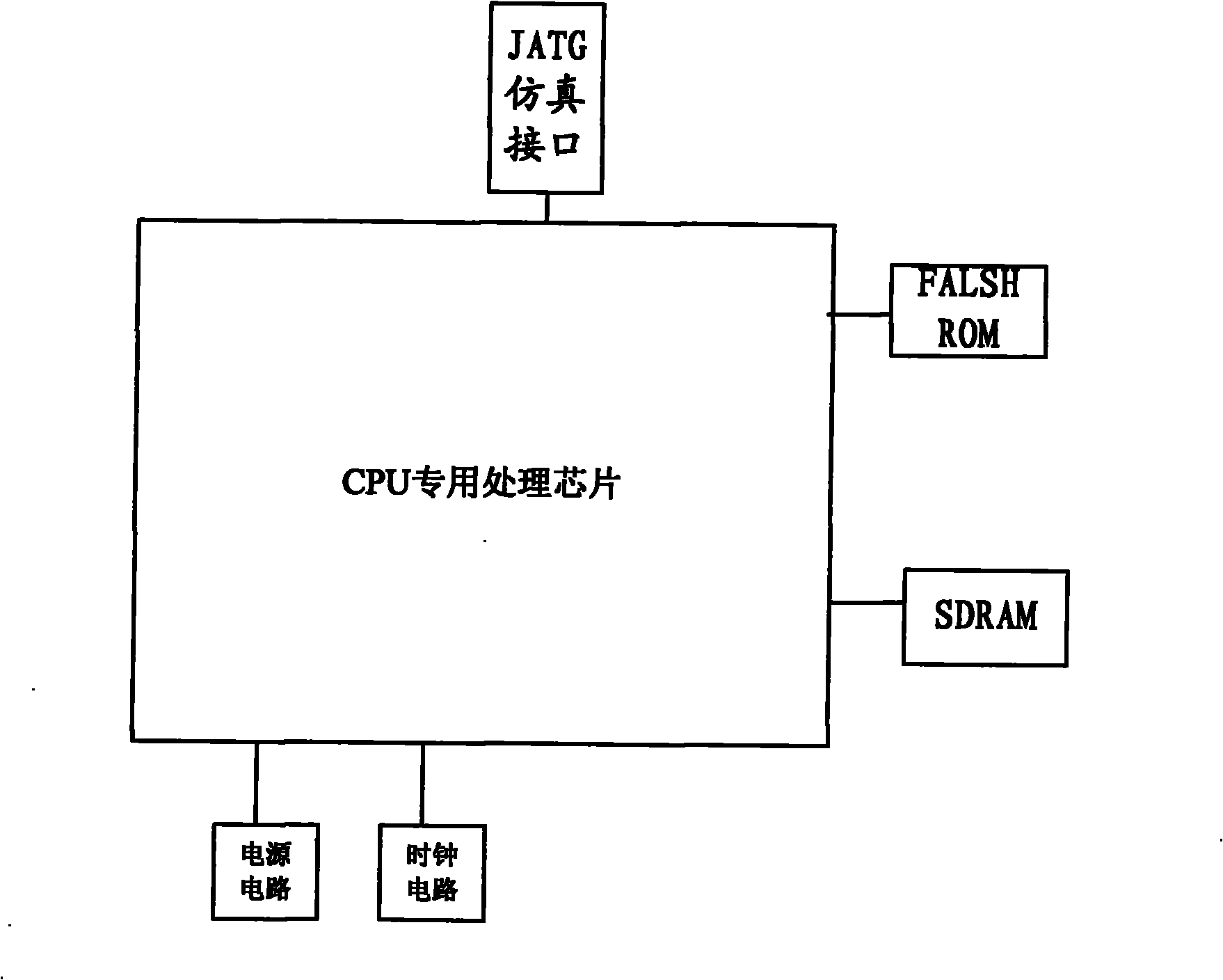
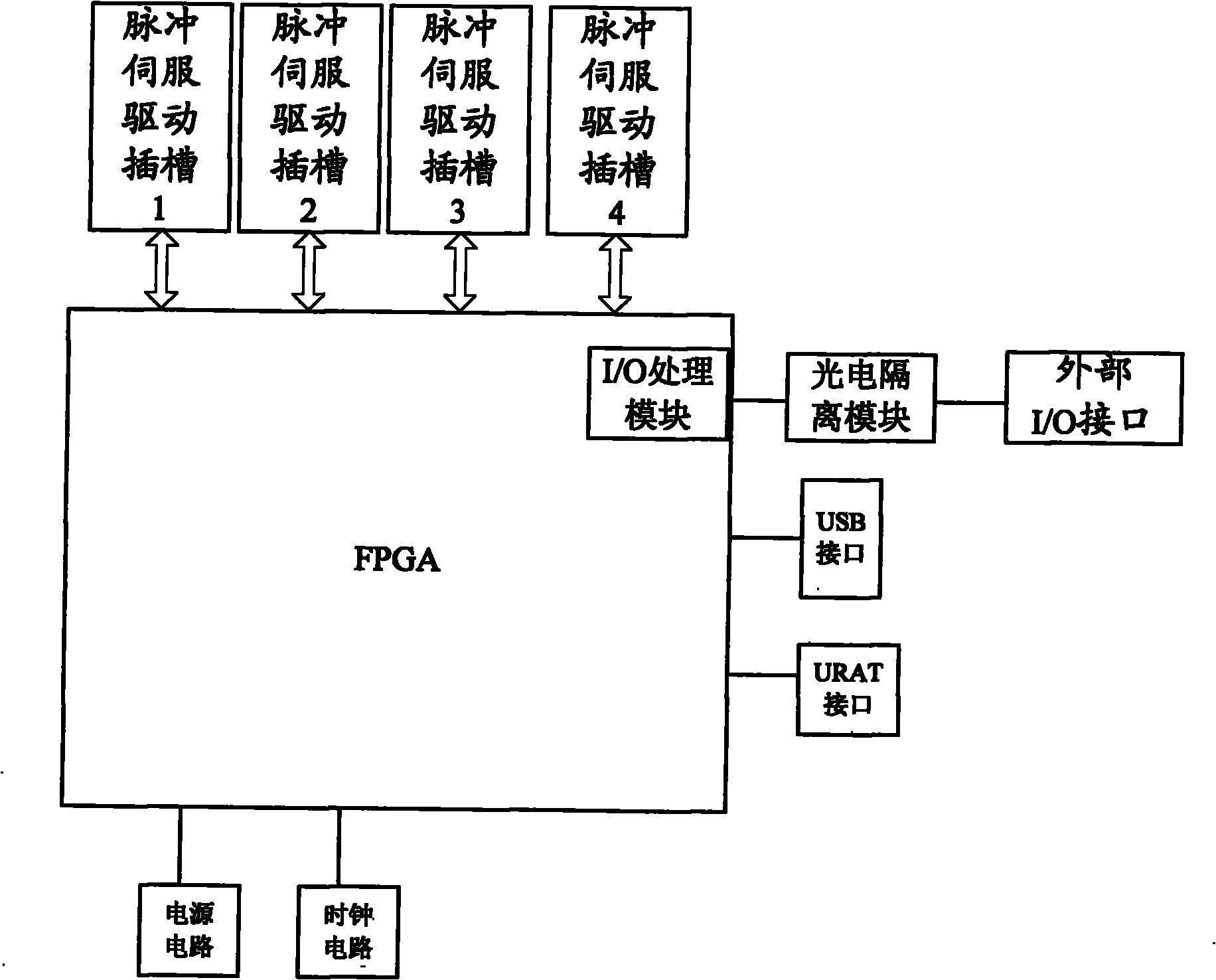
[0043] Such as figure 1 As shown, the scalable and scalable multi-axis motion control system of the present invention is composed of three processing boards, including a CPU core system board, an FPGA base board and a fieldbus servo communication board.

[0044] The CPU core system board and the field bus servo communication board are connected to the FPGA base board through a unified bus slot, and the bus slot is provided with a system internal bus. Specifically, the CPU core system board and the field bus servo communication board are provided with unified slots, and both slots are connected to the FPGA base board through the bus slot at one end of the FPGA base board.

[0045] The FPGA base board, the CPU core system board and the field bus servo communication board are respectively provided with corresponding power circuits, and each power circuit adopts a unified input voltage. The scalable and scalable multi-axis motion control system is equipped with a unified power so...


PUM


Abstract

The invention provides an expandable and cuttable multi-shaft movement control system, which includes a CPU core system board, an FPGA base board, and a fieldbus servo communication board; the CPU core system board and the fieldbus servo communication board are connected with the FPGA base board through a unified bus slot; an FPGA chip on the FPGA base board is connected with an upper computer through a serial bus; the FPGA base board provides multi-shaft pulse type servo drive slots connected with a servo drive system; and the fieldbus servo communication board is connected with a fieldbus, and transmits a movement control order to a bus type servo drive system through the fieldbus. The CPU special processing chip in the invention can select different CPU modules according to actual requirement and function, the fieldbus servo communication board also can be particularly selected according to the actual bus type of the servo drive system, and the multi-shaft movement control order can be transmitted to the servo drive system in the forms of pulse signals and fieldbus protocol signals, so that the expansion and the cut of the number of control shafts can become more convenient.

Description

technical field [0001] The invention relates to the technical field of numerical control, in particular to an expandable and tailorable multi-axis motion control system and method. Background technique [0002] At present, advanced manufacturing equipment such as CNC machine tools, industrial robots, three-coordinate measuring machines and special CNC equipment are developing extremely rapidly, and the intelligent motion control system of these equipment has become a key factor in the realization of their performance and functions. For example, the multi-axis motion control system has been widely used in automation equipment, especially in the field of automatic control of machine tools, light industrial packaging machinery, printing machinery and special CNC processing equipment. [0003] At present, the hardware structure of most motion control systems is relatively fixed. Generally, the CPU, FPGA and servo communication modules are integrated on one circuit board. Modules...

Claims


Application Information

Patent Timeline
IPC IPC(8): G05B19/414
Inventor 高伟强潘伟华沈烈阎秋生卿朝廷黄邹亚
Owner GUANGZHOU LOKSHUN CNC EQUIP
Why Eureka
Try Eureka