Method for removing NOX in flue gas

A technology of nitrogen oxides and flue gas, applied in the field of environmental pollution control, can solve the problems of secondary pollution, low denitrification efficiency, and few, etc., to improve the mixing degree, reduce the ammonia escape rate, improve the utilization rate and denitrification efficiency Effect

Inactive Publication Date: 2013-09-04
CHINESE RES ACAD OF ENVIRONMENTAL SCI
View PDF4 Cites 0 Cited by
  • Summary
  • Abstract
  • Description
  • Claims
  • Application Information

AI Technical Summary

Problems solved by technology

[0009] The two reducing agents are greatly affected by temperature, and the denitrification efficiency is generally low, about 40-60%. At the same time, corrosion and secondary pollution problems are prone to occur
At present, SNCR is rarely used in China, and there are few research results on SNCR denitrification technology.

Method used


Image

  • Method for removing NOX in flue gas
  • Method for removing NOX in flue gas
  • Method for removing NOX in flue gas

Examples


Embodiment 1

[0037] A method for removing nitrogen oxides in flue gas, which is to remove NO in flue gas by using ammonia or urea as a reducing agent X Reduction: The ammonia or urea solution is transported through water vapor and sprayed into the furnace.

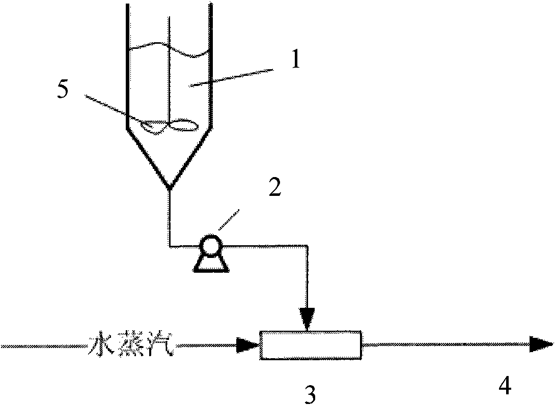
[0038] Such as figure 1 As shown, the urea solution or ammonia solution 1 is delivered to the conveyor 3 through the metering pump 2, and the water vapor is delivered through the conveyor 3, mixed with the water vapor in the conveyor, and sprayed into the furnace. 4 within. A stirrer 5 is provided in the urea solution or ammonia solution.

[0039] When urea is used as the reducing agent, the urea solution is generally about 10% to ensure that the moisture content in the flue gas is within the range of 6-10%. 3 The / NOx molar ratio is 1.2-1.5 (determined according to the efficiency of removing NOx), the boiler waste heat steam at 150-300°C is used to spray the urea solution into the boiler furnace, and the weight ratio of steam to urea solut...

Embodiment 2

[0042] Example 2 Denitration simulation experiment

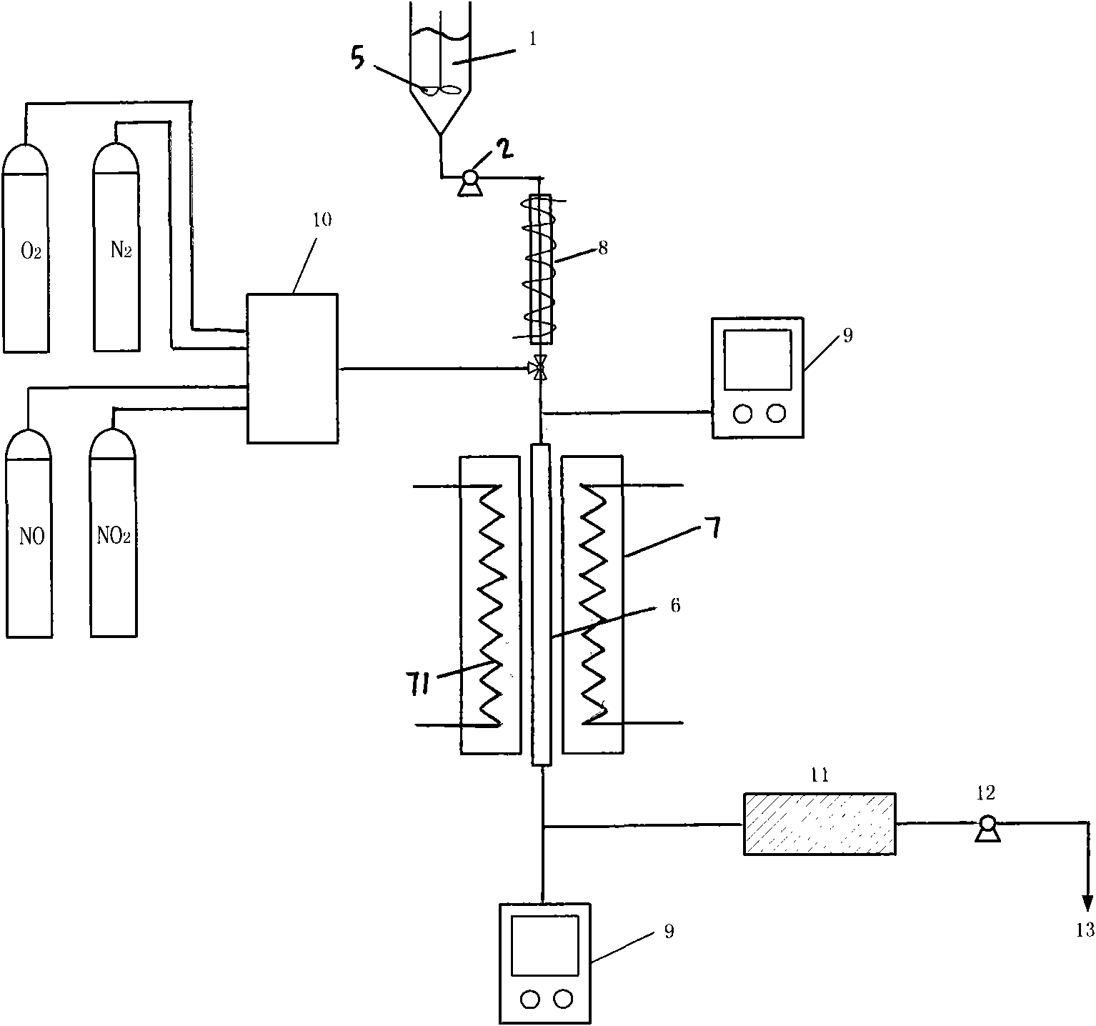
[0043] SNCR denitrification device with simulated flue gas volume of 6L / min, such as figure 2 Shown. The quartz glass SNCR reaction tube 6 with an inner diameter of 30mm and a length of 760mm has a wall thickness of 2mm. The SNCR reaction tube 6 is heated to a maximum of 1300°C by the tubular electric furnace 7 (the tubular electric furnace 7 is equipped with heating resistance wires 71). A program controller 8 adjusts the simulated flue gas temperature, and uses the urea solution 1 as the denitration reducing agent. Control the amount of water vapor for denitrification by changing the concentration of the urea solution and the injection amount, and the NOx concentration of the simulated flue gas is 500mg / Nm 3 . The urea solution is pumped into the simulated flue gas through the metering pump 2 and heated by the program controller 8 into the reaction tube. The reaction system is also provided with a flue gas analyzer 9, a ga...


PUM


Abstract

The invention discloses a method for removing NOX in flue gas, and the method is characterized by reducing the NOX in the flue gas by adopting ammonia or urea as a reducing agent, and spraying the ammonia or urea delivered by virtue of water vapor into a hearth. In the method, the inner energy of waste heat vapor of a boiler is used as a power source; the preheated urea (ammonia) is sprayed into the hearth, so the activity of the reducing agent and the velocity of the reduction action are improved; the water vapor in the flue gas is advantageous to improve the reacting activity of SO2 and a desulfurizing agent; the mixing degree of the flue gas and the reducing gas can be improved, the utilization of the reducing agent and the denitrifying efficiency are improved, and the ammonia escape rate and the N2O emission rate are reduced; and after the reducing agent is heated in advance, the reducing agent is prevented from forming vortex when supercooled air is sprayed into the hearth and from scaling on a water wall tube and a furnace wall.

Description

Technical field [0001] The present invention relates to a new method for removing nitrogen oxides in flue gas by using SNCR, and specifically to a method of using water vapor to transport a reducing agent in an SNCR nitrogen oxide removal process to achieve high-efficiency removal of nitrogen oxides. It belongs to the technical field of environmental pollution control. Background technique [0002] Coal-fired flue gas denitrification technologies mainly include selective catalytic reduction (SCR) and selective non-catalytic reduction (SNCR). SNCR flue gas denitrification technology is different from SCR technology and does not require a catalyst. It uses ammonia or urea as a reducing agent. In the range of 870-1150℃, the NOx reducing agent in the flue gas is changed to N 2 . SNCR technology was first invented by Exxon in the United States and successfully put into industrial application in Japan in 1974. It was later promoted by Fuel Tech in the United States. The United States ...

Claims


Application Information

Patent Timeline
Patent Type & Authority Patents(China)
IPC IPC(8): B01D53/56
CPCY02C20/10
Inventor 王凡张凡朱金伟田刚刘宇王红梅石应杰都基俊
Owner CHINESE RES ACAD OF ENVIRONMENTAL SCI
Why Eureka
Try Eureka