Bridge-vibration intelligent power supply system and method

A power supply system and intelligent power supply technology, applied in the direction of collectors, electromechanical devices, electric vehicles, etc., can solve the problems of affecting the accuracy of data collection, waste of manpower, material and financial resources, unreasonable wiring methods, etc. load and reduce system consumption

Inactive Publication Date: 2011-07-06
CHONGQING JIAOTONG UNIVERSITY
View PDF5 Cites 9 Cited by
  • Summary
  • Abstract
  • Description
  • Claims
  • Application Information

AI Technical Summary

Problems solved by technology

Nowadays, the components of bridge health monitoring are becoming more and more miniaturized and low-power consumption. It takes a waste of manpower, m

Method used


Image

  • Bridge-vibration intelligent power supply system and method
  • Bridge-vibration intelligent power supply system and method
  • Bridge-vibration intelligent power supply system and method

Examples


Embodiment 1

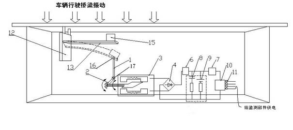
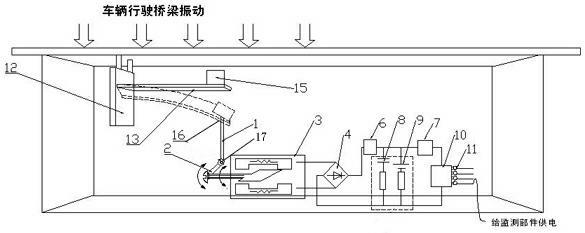
[0034] Such as figure 1 As shown, the bridge vibration intelligent power supply system of the present invention includes an energy conversion device, an electric energy storage device and a power management device;

[0035] The energy conversion device includes a pressure transmission mechanism, a connecting rod 1, a crank 2 and a generator 3. The vibration transmission mechanism is detachably connected to the bottom surface of the bridge. One end of the connecting rod 1 is connected to the vibration transmission mechanism. The other end of the rod 1 is connected to the crank 2, and the vibration transmission mechanism transmits the vibration pressure of the bridge to the connecting rod 1, and then to the crank 2 through the connecting rod, and the crank 2 is connected to the input shaft of the generator 3, when the input shaft When rotating, it drives the coil inside the generator to rotate, cuts the magnetic field generated by the permanent magnet, and generates electricity;...

Embodiment 2

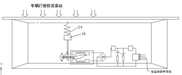
[0042] The difference between this embodiment and Embodiment 1 is that the vibration transmission mechanism includes if a spring 14 is used, one end of the spring 14 is connected to the bottom surface of the bridge, the other end of the spring 14 is hung with a mass block 15, and the lower end of the mass block 15 The end face is connected with the connecting rod 1.

[0043] When the vehicle passes through the bridge and vibrates, the spring moves up and down in the axial direction, which drives the movement of the mass block, further drives the interaction between the connecting rod and the crankshaft, and makes the input shaft of the generator rotate to generate electric energy.

[0044] In comparison, the cantilever beam in Embodiment 1 bears more stress loads and has stronger fatigue resistance; while the spring in Embodiment 2 has simple structure, pure function, easy installation and lighter weight. Both require the use of materials with a high elastic coefficient, and c...


PUM


Abstract

The invention discloses a bridge-vibration intelligent power supply system, which comprises an energy conversion device, an electric energy accumulation device and a power source management device, wherein the energy conversion device comprises a vibration transmission mechanism, a connecting rod, a crank and an engine; the vibration transmission mechanism transmits the vibration pressure of a bridge to a connecting rod firstly and then to the crank through the connecting rod; the crank is connected with an input shaft of the engine and used for driving the input shaft of the engine to rotateand generate electricity; the electric energy accumulation device comprises a rectification circuit, a conversion/process circuit I, a conversion/process circuit II, a super capacitor and a storage battery; the power source management device comprises an electric energy management controller and power source channels, a power source input terminal of the electric energy management controller is connected with a power source output terminal of an energy management device, and is connected with monitoring devices of bridges through a plurality of power source channels. The bridge-vibration intelligent power supply system has a compact structure, fully utilizes vibration pressure of the bridge when vehicles move on the bridge, and achieves the purposes of saving energy and electricity and ensuring the uninterrupted operation of the monitoring parts.

Description

technical field [0001] The invention relates to the technical field of bridge monitoring, in particular to a system for realizing intelligent power supply of monitoring components by using bridge vibration, and also relates to an intelligent power supply method. Background technique [0002] Bridges are one of the important infrastructures of the country. With the rapid development of bridge construction, people pay more and more attention to bridge safety issues. As the service period continues, the bridge structure may deteriorate, and the increasing traffic volume and overloading may exceed the original design standards, thereby reducing the reliability of the bridge, and even causing bridge safety problems, leading to catastrophic disasters. ACCIDENT. The construction and maintenance of large bridges requires a lot of manpower, material and financial resources, lagging behind the comprehensive monitoring and evaluation methods of bridge construction and development, so ...

Claims


Application Information

Patent Timeline
IPC IPC(8): H02J7/32H02K7/18
Inventor 张奔牛唐练
Owner CHONGQING JIAOTONG UNIVERSITY
Why Eureka
Try Eureka