Single fiber bi-directional optical element and assembly method thereof

A single-fiber bidirectional, optical component technology, applied in the field of optical network devices, can solve the problems of low production efficiency, high cost, and inability to produce in large quantities, and achieve the effect of improving packaging efficiency and reducing production costs

Inactive Publication Date: 2011-07-06
HUAWEI MACHINERY
View PDF3 Cites 10 Cited by
  • Summary
  • Abstract
  • Description
  • Claims
  • Application Information

AI Technical Summary

Problems solved by technology

The packaging method of the above-mentioned BOSA determines that it cannot be placed by automatic placement equipment. This is because the current automatic placement equipment must first identify the target position where the material is placed, and then identify the alignment position of the material, and use the manipulator to place the material. Move the alignment position to the target position
In the BOSA device of the above-mentioned traditional structure, the target position is the center of the receiv

Method used


Image

  • Single fiber bi-directional optical element and assembly method thereof
  • Single fiber bi-directional optical element and assembly method thereof
  • Single fiber bi-directional optical element and assembly method thereof

Examples


Embodiment 1

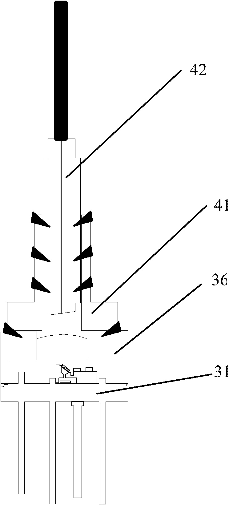
[0030] image 3 It is an axial sectional view of an embodiment of the single-fiber bidirectional optical component provided by the present invention, Figure 4 Yes image 3 Axial cross-sectional view of other structures except optical fiber and its fixing parts in . The single-fiber bidirectional optical component in this embodiment is a pigtail type single-fiber bidirectional optical component, and the alignment optical interface is an optical fiber.

[0031] like image 3 and Figure 4 As shown, the single-fiber bidirectional optical component in this embodiment includes a stem 31 on which a base 32 is fixed, and a filter 34 and a laser 33 are fixed on the base 32 . In this embodiment, the laser 33 may be a laser diode (LD). The light output from the laser 33 enters the pigtail 42 after being reflected by the filter 34 . The fixing method between the laser 33 and the base 32 can be adhesive bonding, eutectic welding or laser brazing, and the fixing method between the f...

Embodiment 2

[0045] Figure 5 It is an axial sectional view of another embodiment of the single-fiber bidirectional optical component provided by the present invention, such as Figure 5 As shown, the single-fiber bidirectional optical component in this embodiment is a pluggable single-fiber bidirectional optical component.

[0046] The single-fiber bidirectional optical component in this embodiment includes a stem 51 on which a base 52 is fixed, and a filter 54 and a laser 53 are fixed on the base 52 . The laser 53 can be a laser diode. The light output from the laser 53 enters the pigtail 52 after being reflected by the filter 54 . The fixing method between the laser 53 and the base 52 can be adhesive bonding, eutectic welding or laser brazing. The fixing methods between the base 52 and the stem 51 include but not limited to adhesive bonding, eutectic bonding, laser brazing or laser welding. A photoelectric conversion device 55 fixed on the stem 51 is arranged below the base 52 and a...


PUM


Abstract

The embodiment of the invention discloses a single fiber bi-directional optical element and an assembly method thereof. The single fiber bi-directional optical element comprises a tube socket, wherein a base is fixed on the tube socket; a filter and a laser are fixed on the base; a photoelectric conversion device fixed on the tube socket is arranged below the base and corresponds to the filter; a ray transmitting hole is formed on the base and between the filter and the photoelectric conversion device; and rays emitted by the laser and rays received by the photoelectric conversion device coincide at the incidence point on the filter. The single fiber bi-directional optical element and the assembly method thereof have the advantages that the encapsulation efficiency is high and the large-batch production is facilitated.

Description

technical field [0001] The invention relates to the field of optical network devices, in particular to a single-fiber bidirectional optical component and a packaging method thereof. Background technique [0002] With the evolution of fiber-to-copper networks, FTTX (Fiber To The X) has become the mainstream technology for access networks. At present, the main method of FTTX is PON (Passive Optical Network, Passive Optical Network), and the key photoelectric modules of PON access equipment are ONU (Optical Network Unit, Optical Network Unit) and OLT (Optical Line Terminal, Optical Line Terminal). Among them, ONU is a module placed directly on the user side, which is extremely sensitive to cost. In ONU and OLT, about 70% of the total cost is BOSA (BI-Direction Optical Sub-Assembly, single-fiber bidirectional optical component) optical device. [0003] The structure and packaging process of the traditional BOSA determine that the manufacturing cost of the BOSA is relatively hig...

Claims


Application Information

Patent Timeline
IPC IPC(8): H04B10/12H04B10/25
Inventor 曾同新
Owner HUAWEI MACHINERY
Why Eureka
Try Eureka