Circulating liquid phase hydrogenation method

A technology of circulating fluid and circulating oil, which is applied in hydrocarbon oil cracking, petroleum industry, processing hydrocarbon oil, etc., can solve the problems of increasing high-pressure gas system equipment, high pipeline size, and increasing investment in equipment construction, saving construction investment, The effect of reducing the size of the pipe

Active Publication Date: 2011-07-13
CHINA PETROCHEMICAL CORP +1
View PDF4 Cites 33 Cited by
  • Summary
  • Abstract
  • Description
  • Claims
  • Application Information

AI Technical Summary

Problems solved by technology

The larger flow rate of circulating hydrogen increases the size of high-pressure gas system equipmen

Method used


Image

  • Circulating liquid phase hydrogenation method
  • Circulating liquid phase hydrogenation method
  • Circulating liquid phase hydrogenation method

Examples


Example Embodiment

[0078] Examples:

[0079] The following is a preferred embodiment of the present invention, through which the method of the present invention is specifically described, but the scope of the present invention is subject to the protection scope of the claims and is not limited by the preferred embodiment.

[0080] a) The raw oil used is diesel.

[0081] b) The purity of the supplemental hydrogen component is preferably 85-99.9V% of hydrogen, 0.01-6V% of methane, and 0-2V% of hydrogen sulfide.

[0082] c) The processing scheme adopted is diesel hydrofining.

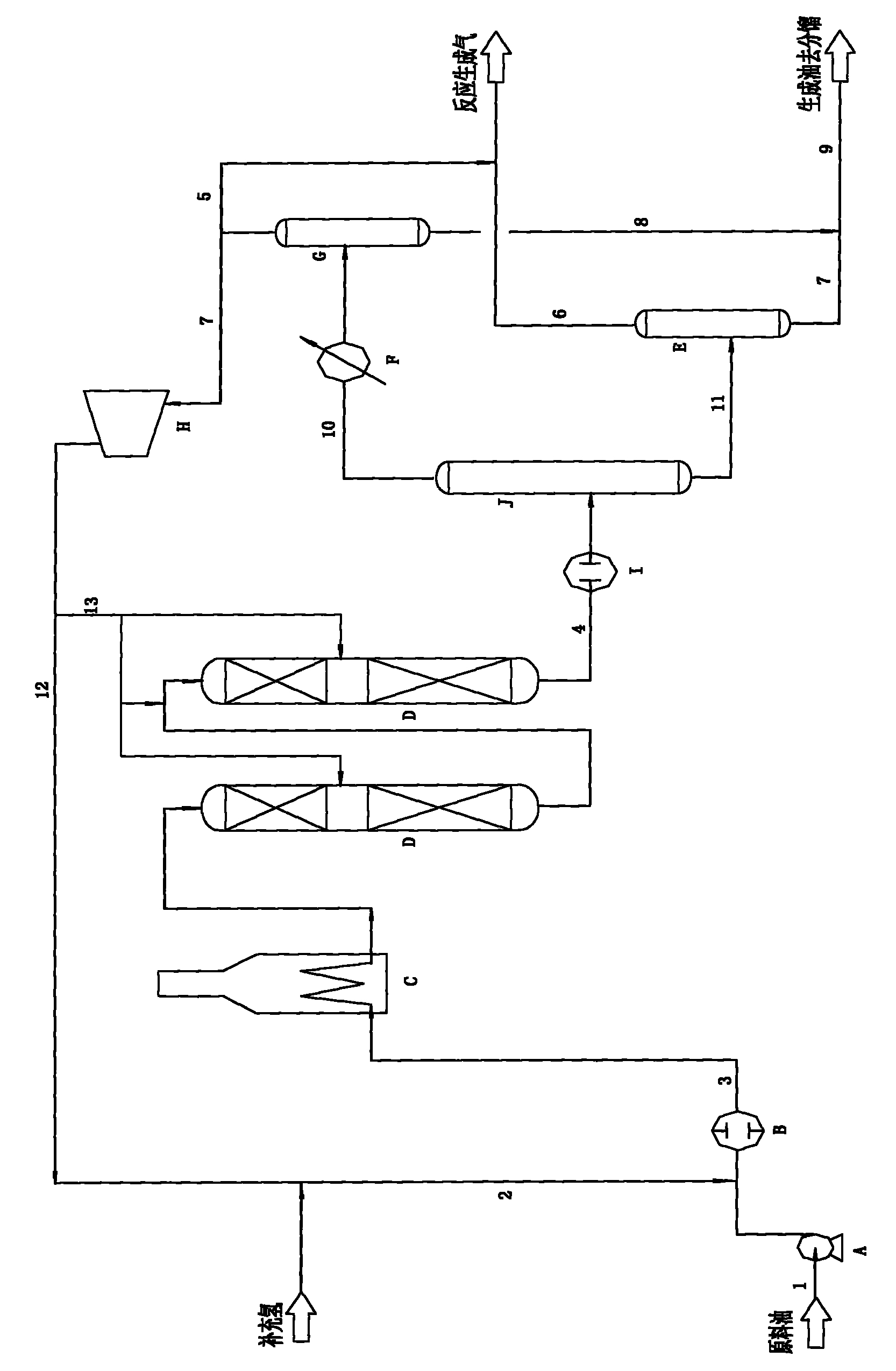
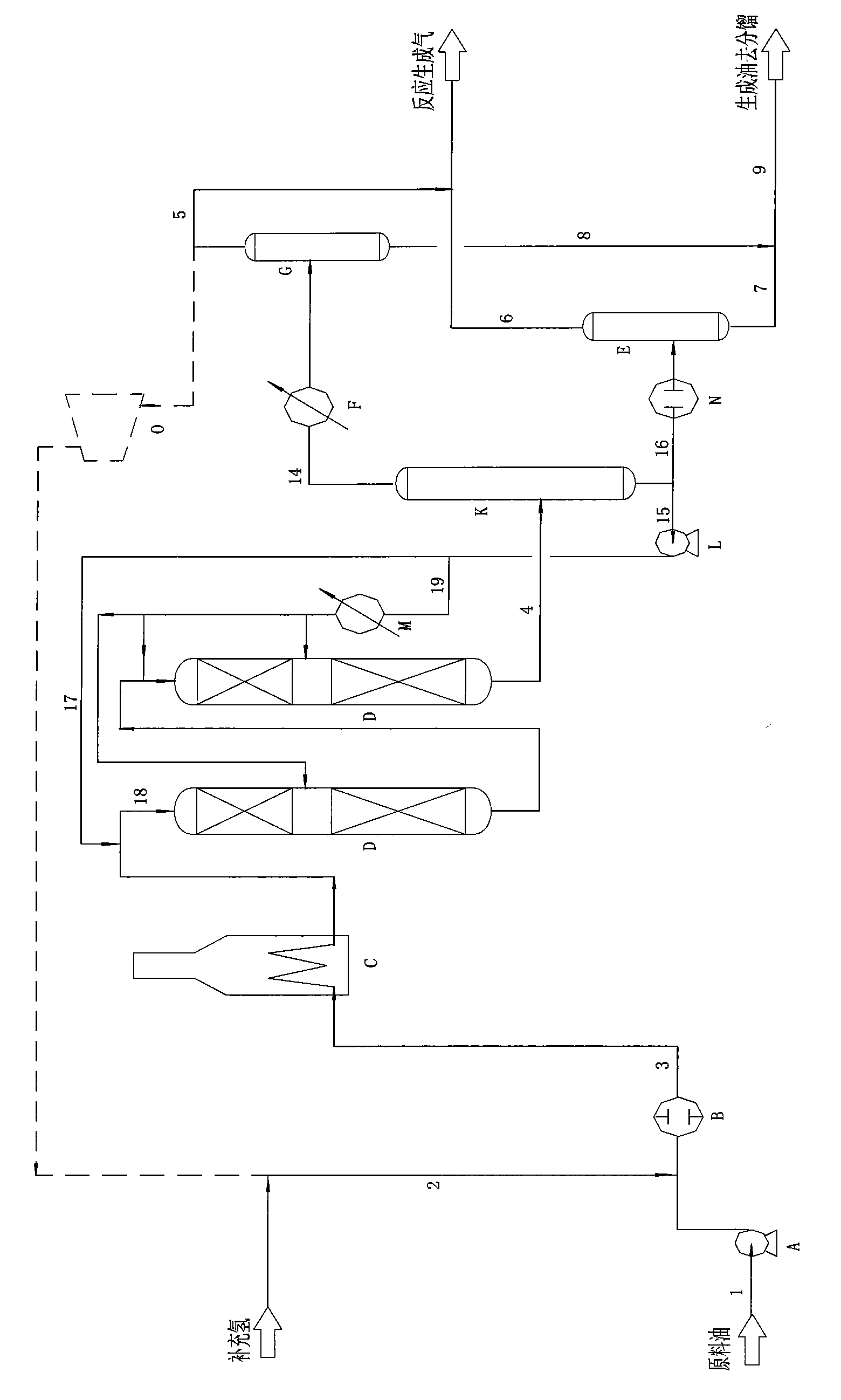
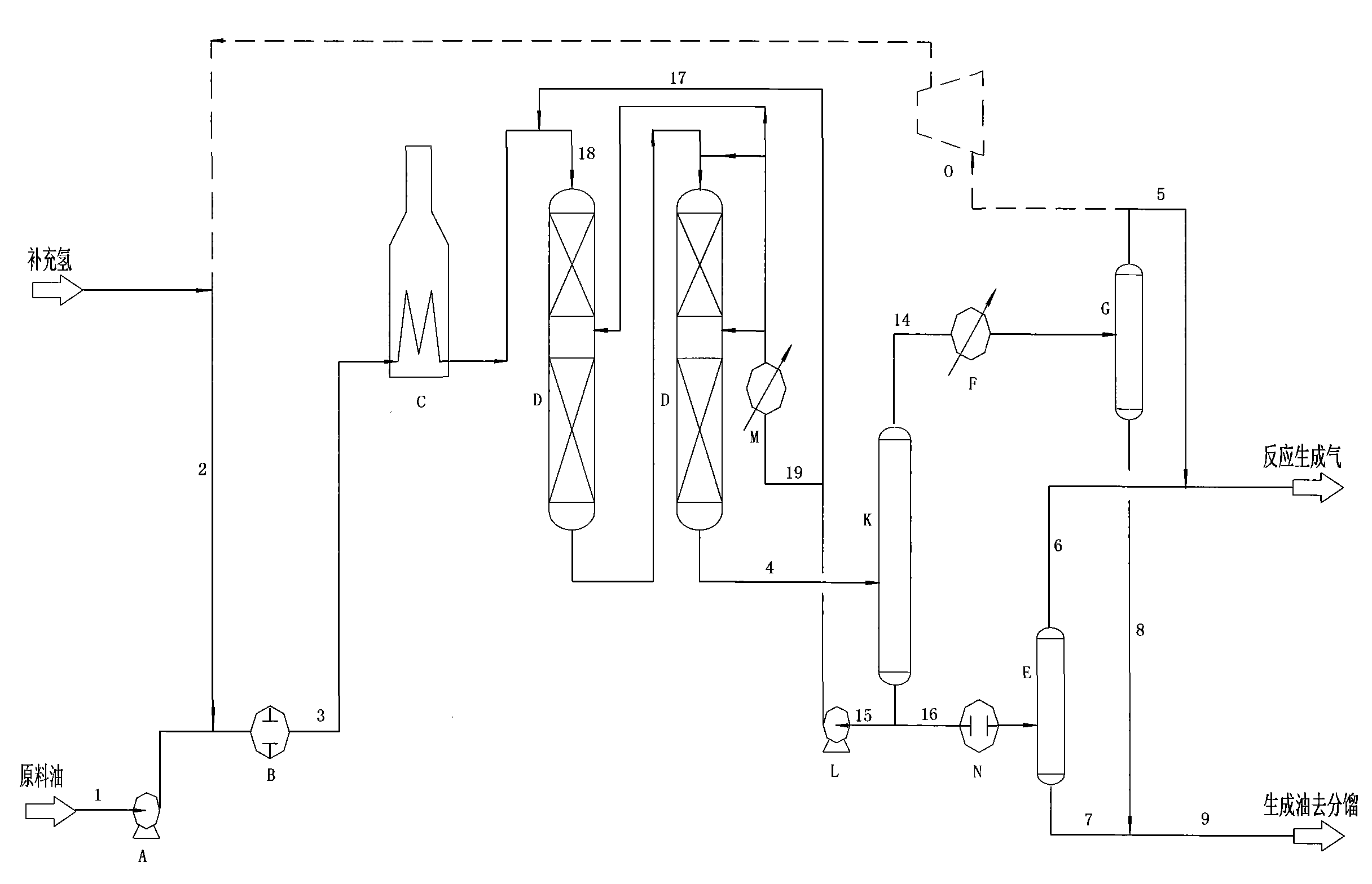
[0083] d) After the hydrogenation reaction product leaves the reactor, it can enter the hot high-pressure separation tank through appropriate heat exchange, and the cooling temperature ranges from 10-200°C. Preferably, the reaction product directly enters the hot high-pressure separation tank without heat exchange.

[0084] e) The circulating pump can be arranged at the liquid phase outlet of the hot low pressure separation tank, prefe...


PUM


Abstract

The invention relates to a circulating liquid phase hydrogenation method which is characterized in that the hydrogenation reaction product is cooled by a heat exchanger or directly enters a thermal high-pressure separating tank; part of the liquid phase stream separated out from the thermal high-pressure separating tank is directly used as circulating oil or is further separated by the thermal high-pressure separating tank to be used as circulating oil, and the circulating oil returns to the inlet of each hydrogenation reactor and/or the inter-bed inlet space of the multi-bed hydrogenation reactor; the inlet of each hydrogenation reactor and/or the inter-bed inlet space of the multi-bed hydrogenation reactor are/is provided with or not provided with an circulating oil cooler; and after being subjected to cooling and liquid separation, the gas phase stream separated from the thermal high-pressure separating tank is sent out as the reaction generation gas or is compressed before returning to a hydrogen gas feed system. The method provided by the invention reduces the high-pressure gas passage system equipment in the existing hydrogenation method, the size of the pipeline and the energy consumption of the device, and achieves the purpose of saving the construction investment of the device.

Description

technical field [0001] The invention belongs to the oil product hydrogenation process flow method. Background technique [0002] The raw oil referred to in the present invention is the distillate oil of petroleum processing, such as including: naphtha, kerosene, diesel oil, wax oil, atmospheric residue, vacuum residue, and any mixing ratio of the above-mentioned oil products. [0003] The hydrogenation method referred to in the present invention includes methods such as hydrofinishing, hydrotreating, hydroupgrading, hydrocracking and residue hydrogenation of the above-mentioned distillate oil. [0004] figure 1 For the existing distillate oil hydrogenation method, the process description is as follows: [0005] After the raw material oil 1 is boosted by the reaction feed pump A, it is first mixed with hydrogen 2, then exchanged heat through the raw material heat exchanger B, and then enters the reaction heating furnace C to be heated to the temperature required for the rea...

Claims


Application Information

Patent Timeline
IPC IPC(8): C10G45/00C10G47/00C10G49/00
Inventor 刘凯祥李浩孙丽丽刘家明
Owner CHINA PETROCHEMICAL CORP
Why Eureka
Try Eureka