Magnetic conductive wire as well as electronic equipment and manufacturing method thereof

A technology of electronic equipment and magnetic wire, applied in the field of magnetic wire, can solve the problems of overcoming eddy current, resistance drop, inability to overcome proximity effect and skin effect, etc., and achieve the effect of suppressing the formation of eddy current and reducing AC resistance

Inactive Publication Date: 2011-07-13
ELECTRIC WIRE & CABLE
View PDF3 Cites 9 Cited by
  • Summary
  • Abstract
  • Description
  • Claims
  • Application Information

AI Technical Summary

Problems solved by technology

[0008] The purpose of the present invention is to solve the problem that the existing magnetic resistance enameled wire in the prior art cannot increase the content of the magnetic resistance material while maintaining the orig

Method used


Image

  • Magnetic conductive wire as well as electronic equipment and manufacturing method thereof
  • Magnetic conductive wire as well as electronic equipment and manufacturing method thereof
  • Magnetic conductive wire as well as electronic equipment and manufacturing method thereof

Examples


Embodiment

[0046] Instructions for materials and equipment used:

[0047] 1. Polyurethane coating: Produced by ASEAN Chemical Industry, model PU-130-45, viscosity at 30°C is 0.5 Pa·s (Pa·s), solid content 45%.

[0048] 2. γ-Fe2O3: produced by Japan Titan Kogyo Company, model γ-MRD, with an axial length of 0.5 μm and an axial ratio of 7.

[0049] 3. Oleic acid: produced by Japan Shimahisa Co., Ltd., CAS No.112-80-1, concentration 98%.

[0050] 4. Inductance, capacitance and resistance measuring instrument (LCR Meter): manufactured by Agilent, USA, model E4980A, the test frequency range is 20Hz to 2MHz.

Embodiment 1

[0059] Add 20 parts of γ-Fe2O3 to 100 parts of polyurethane paint, knead in a ball mill for 24 hours to make a magnetic paint, and apply a single layer on a copper material with a wire diameter of 0.31 mm to make a wire sample according to the following conditions. The characteristics of the finished product are shown in Table 1. Show.

[0060] Coating method: eye mold

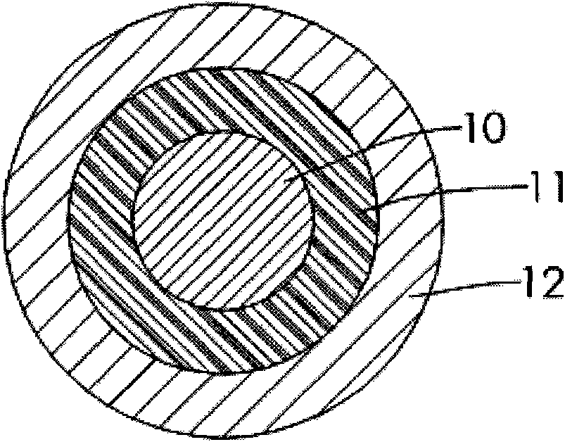
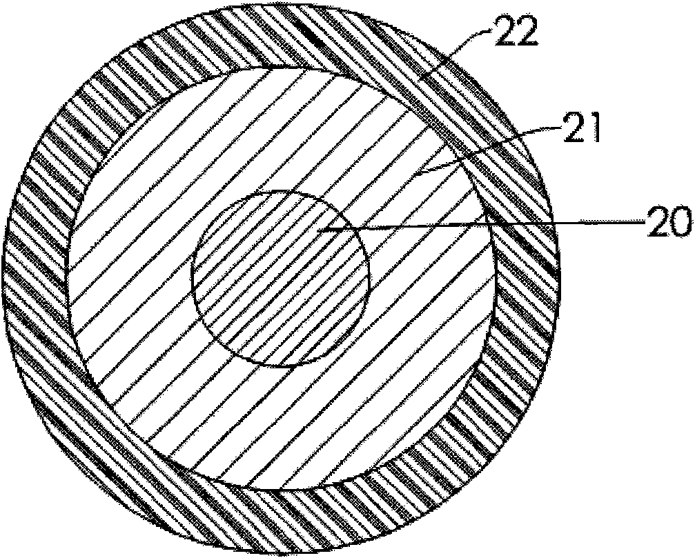
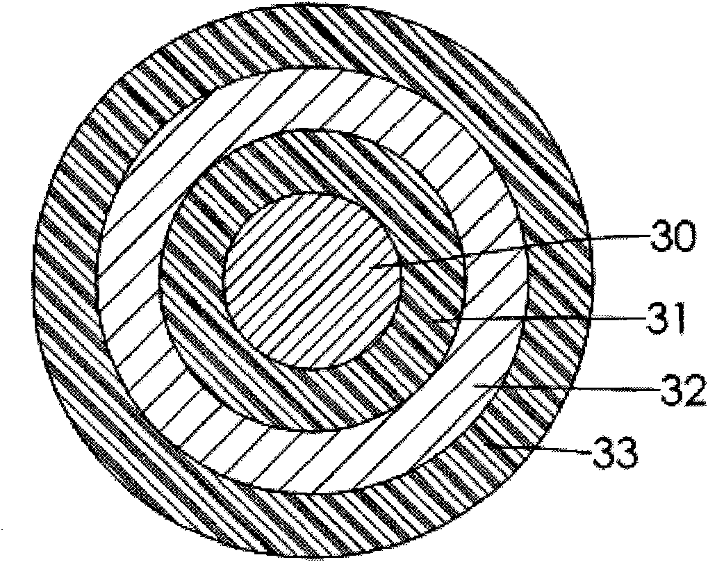
[0061] Coating times: Alternately apply magnetic paint 5 times and polyurethane paint 5 times (such as figure 2 shown)

[0062] Line speed: 60-70 m / min

[0063] Baking oven temperature: 440-500°C

Embodiment 2

[0065] After modifying the surface of 20 parts of γ-Fe2O3 with 5 parts of oleic acid, add 100 parts of polyurethane paint together, and mix it with a ball mill for 24 hours to make a magnetic paint. According to the conditions of Example 1, a single layer is coated on a copper wire with a wire diameter of 0.31 mm. The wire samples were made on the material, and the characteristics of the finished products are shown in Table 1.


PUM

PropertyMeasurementUnit
The average particle sizeaaaaaaaaaa

Abstract

The invention discloses a magnetic conductive wire comprising a conducting wire body, and at least one magnetic paint layer and at least one insulated paint layer which are coated at the outer side of the conducting wire body and arranged in a mutually staggered manner, wherein the magnetic material in the magnetic paint layer is non-electrically conductive. Magnetic paint is formed by adding the magnetic material to the insulated paint, and the magnetic paint and the non-magnetic insulated paint are coated at the outer side of the conducting wire body in a staggered manner, thus magnetic field interference generated after the galvanization of the conducting wire body is guided or offset by using the magnetic material, the formation of eddy current of the conducting wire is effectively inhibited, and the purpose of reducing alternating current resistance is achieved.

Description

technical field [0001] The invention relates to a magnetic wire, in particular to a magnetic wire which utilizes magnetic materials to generate interference or guiding effects on the magnetic field lines of the wire itself to overcome the proximity effect and skin effect, thereby reducing high-frequency AC resistance and saving energy loss. Background technique [0002] Commonly used devices such as coils and transformers mainly use the principle of electromagnetic induction to achieve the purpose of controlling inductance or converting voltage. However, energy will be lost in each conversion of electric energy and magnetic energy, especially in high-frequency working environments. The phenomenon of energy loss is more obvious. The energy loss at high frequency mainly comes from eddy current loss, including the iron loss caused by the iron core and the copper loss from the enameled wire. The cause of the eddy current is that the magnetic flux passing through the conductor c...

Claims


Application Information

Patent Timeline
IPC IPC(8): H01B7/02H01B3/00H01B13/00H01F1/14H01F1/34
Inventor 方沧泽钟瀚扬洪启峰吕亭宜周广强庄博贵陈俊宏邱荣焜沈尚慧
Owner ELECTRIC WIRE & CABLE
Why Eureka
Try Eureka