Tunable Bragg stack

A device, alternating layer technology, used in lasers, nanotechnology, instruments, etc., can solve problems such as refractive index changes

Active Publication Date: 2011-07-13
OPALUX
View PDF6 Cites 18 Cited by
  • Summary
  • Abstract
  • Description
  • Claims
  • Application Information

AI Technical Summary

Problems solved by technology

[0008] Currently, tuning of the structural color in such one-dimensional photonic crystal structures comes only from the adso

Method used


Image

  • Tunable Bragg stack
  • Tunable Bragg stack
  • Tunable Bragg stack

Examples


Embodiment

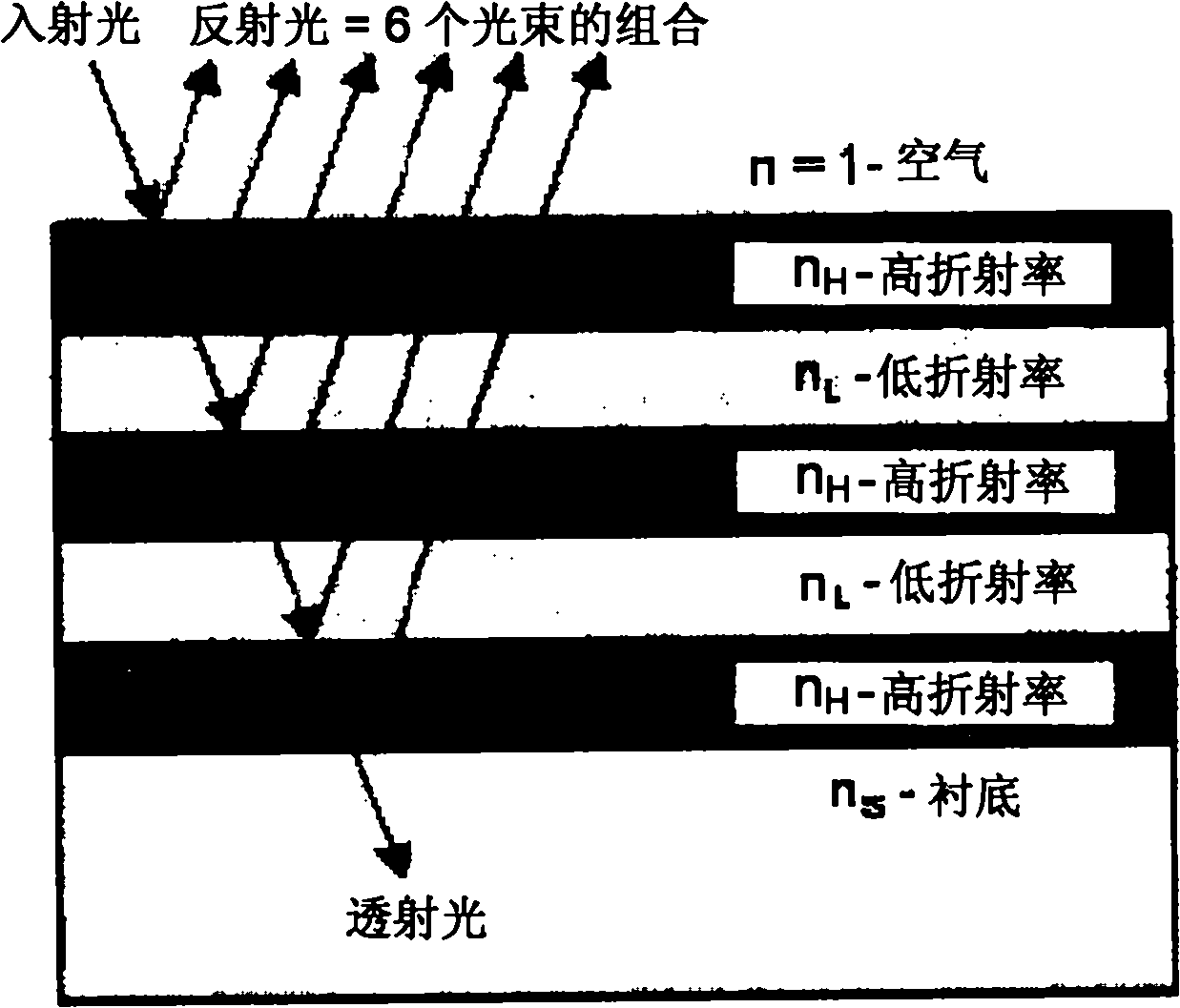
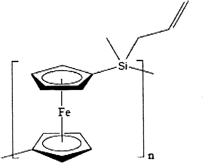
[0103] One example of an electrically tunable DBR is a composite polyferrocenesilane / nanoparticle DBR. The DBR comprises alternating layers of different nanoparticle layers, which are infiltrated with polyferrocenesilane (PFS). This structure can be used in electrochemical cells by first fabricating a composite DBR on a conductive electrode (e.g., fluorine-doped tin oxide, which can be transparent), and then integrating the DBR and its electrodes into an electrolytic electrochemical cell. Battery.

[0104] SiO 2 and TiO 2are two materials that can be used to build DBR structures. These two materials have different dielectric constants and can also be grown as highly uniform thin films using a wide range of techniques such as pulsed laser deposition, reactive sputtering or different types of chemical vapor deposition techniques (Jethmalani et al., Langmuir, 1997, Vol. 13, p. 2633). Furthermore, a combination of dip coating (Chen et al., Appl. Phys. Lett, 1999, Vol. 75, p. ...


PUM

PropertyMeasurementUnit
Cross section sizeaaaaaaaaaa
Sizeaaaaaaaaaa

Abstract

A tunable photonic crystal device comprises: alternating layers of a first material and a second material, the alternating layers comprising a responsive material, the responsive material being responsive to an external stimulus, the alternating layers having a periodic difference in refractive indices giving rise to a first reflected wavelength; wherein, in response to the external stimulus, a change in the responsive material results in a reflected wavelength of the device shifting from the first reflected wavelength to a second reflected wavelength.

Description

technical field [0001] The present disclosure relates to tunable photonic crystals. In particular, the present disclosure relates to tunable one-dimensional photonic crystals. Background technique [0002] For many years, the field of photonic crystals (PC) has received great attention from researchers in academia and industry. Such materials are of interest because they interact with visible light through periodic spatial modulation of their refractive index. In particular, the periodic refractive index modulation present in PCs leads to the selective reflection of light with wavelengths corresponding to the periodicity of this modulation. One interaction of interest occurs when the periodicity of the refractive index of PC is comparable to the wavelength of visible light (Arsenault et al., Adv. Mater, 2003, Vol. 6, p. 503). This causes an interaction with light perceptible to the naked eye. [0003] Photonic crystals can be prepared in one-dimensional, two-dimensional ...

Claims


Application Information

Patent Timeline
IPC IPC(8): G02F1/19G01R19/145G09F13/00G09G3/20H01L33/00H01S5/125H01S5/187H01L33/46
CPCH01S3/08059G02F2001/1515G02F1/0128G02F2201/346G02F1/0147G02F1/21G02F1/15G02F2202/32B82Y20/00G02F2001/151H01L33/46G02F1/03H01L2933/0083Y10S977/773G02F1/009G02F1/15165G02F2001/1518H01L2924/0002H01L2924/00G02B26/00G02F1/19G09G3/20H01L33/00H01S5/125H01S5/187
Inventor 安德烈·阿森奥尔特格奥弗里·阿兰·奥辛丹尼尔·帕特里克·普佐
Owner OPALUX
Why Eureka
Try Eureka