Energy-saving control system of injection machine

An energy-saving control system and technology for injection molding machines, applied in the field of energy-saving control systems for injection molding machines, can solve problems such as increased wear, increased labor costs, and insufficient stability of motion coordination, and achieve the effects of reduced wear and good buffering effects

Inactive Publication Date: 2011-07-27
WENZHOU ANXIN TECH +1
View PDF8 Cites 2 Cited by
  • Summary
  • Abstract
  • Description
  • Claims
  • Application Information

AI Technical Summary

Problems solved by technology

However, first, since the double-volume plunger pump supplies oil through the reciprocating movement of the plunger, during the flow switching process, there is a breakpoint on the pressure supply due to the discontinuity of the oil pressure, and when the oil pressure is injected The moment when the breakpoint occurs affects the accuracy of product quality; second, due to the precise production of the plunger, the quality of the oil is high, and the liquid containing suspended solids cannot be transported; third, due to the complex mechanical structure of the plunger pump, the moving body Many, so the noise is the largest of all pumps
[0005] In addition, if the movement coordination of various mechanisms in the injection molding machine system is not stable enough, especially if the transmission between the servo motor and the double-volume plunger pump is not stable and smooth, it will increase the wear of the transmission mechanism between the servo motor and the double-volume plunger pump and thus cause unnecessary energy loss
If timely maintenance is not carried out, the energy consumption of the injection molding machine system will be increased; if real-time maintenance is carried out, labor costs will inevitably be increased
And when the injection molding machine system is working, the servo motor will generate vibration. If the vibration is not well controlled, it will also increase wear and tear, thereby increasing the energy consumption and operating cost of the injection molding machine system.

Method used


Image

  • Energy-saving control system of injection machine
  • Energy-saving control system of injection machine
  • Energy-saving control system of injection machine

Examples


Embodiment Construction

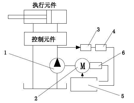
[0020] Such as figure 1 As shown, this embodiment includes an internal gear pump 1, a servo motor 2, a pressure sensor 3, a digital-to-analog converter 4 and a controller 5, the pressure sensor 3 is electrically connected to the digital-to-analog converter 4, and the digital-to-analog converter 4 is electrically connected to the digital-to-analog converter. The converter 4 is electrically connected to the controller 5, the controller 5 is electrically connected to the servo motor 2 and controls the action of the servo motor 2, and the pressure sensor 3 is arranged at the outlet of the internal gear pump 1. At the oil port, it is used to detect the liquid pressure output by the internal gear pump 1, and transmit the detected signal to the digital-to-analog converter 4, and the digital-to-analog converter 4 converts the detected analog signal to Become digital signal soldier and send to described controller 5. The servo motor 2 is also provided with a pulse encoder 6 for detect...


PUM


Abstract

The invention provides an energy-saving control system of an injection machine, comprising a servo motor, a pressure sensor, a D / A (Digital / Analog) converter and a controller. The pressure sensor is electrically connected with the D / A converter which is electrically connected with the controller; and the controller is electrically connected with the servo motor and controls the servo motor to actuate. The control system also comprises an internal engaged gear pump, and the pressure sensor is arranged at the oil outlet of the internal engaged gear pump and used for detecting the pressure of liquid output by the internal engaged gear pump and conveying a detected signal to the D / A converter which converts the detected analog signal into a digital signal and transmits the digital signal to the controller. The internal engaged gear pump has the advantages of simple and compact structure, low working abrasion and smaller ripple and noise, and especially has low requirement on the cleanness of oil liquid without regularly checking or filtering the oil liquid, thereby greatly reducing unnecessary working hour waste of workers.

Description

technical field [0001] The invention relates to an energy-saving control system for an injection molding machine. Background technique [0002] Injection molding machine industry is an industry closely related to national production and life, ranging from automobiles and moulds, to household appliances, toys, mobile phones, etc., are inseparable from injection molding processing. Injection molding machines are the main production equipment in the plastics industry. Injection molding machine is a special plastic molding machine. It uses the thermoplasticity of plastic. After heating and melting, high pressure is applied to make it flow into the mold cavity quickly. After a period of pressure maintaining and cooling, it becomes plastic products of various shapes. The process of an injection molding machine is generally divided into six stages: clamping, injection, melting, pressure holding, cooling, mold opening, and ejection, which are cycled in sequence. Each stage requires ...

Claims


Application Information

Patent Timeline
Patent Type & Authority Applications(China)
IPC IPC(8): B29C45/76
Inventor 刘建寅刘建亮
Owner WENZHOU ANXIN TECH
Why Eureka
Try Eureka