
Dual-motor rotating speed coupling drive assembly

A drive assembly, dual motor technology, applied in the direction of electric power unit, power unit, control device, etc.

Inactive Publication Date: 2011-07-27
BEIJING INSTITUTE OF TECHNOLOGYGY
View PDF4 Cites 50 Cited by
  • Summary
  • Abstract
  • Description
  • Claims
  • Application Information

AI Technical Summary

Problems solved by technology

The dual-motor speed coupling drive assembly provides a new technical approach to solve the transmission system's large-scale non-power interruption torque change, stepless speed change and high reliability.

Method used


Image

  • Dual-motor rotating speed coupling drive assembly
  • Dual-motor rotating speed coupling drive assembly
  • Dual-motor rotating speed coupling drive assembly

Examples


Embodiment Construction

[0008] Now further illustrate in conjunction with accompanying drawing.

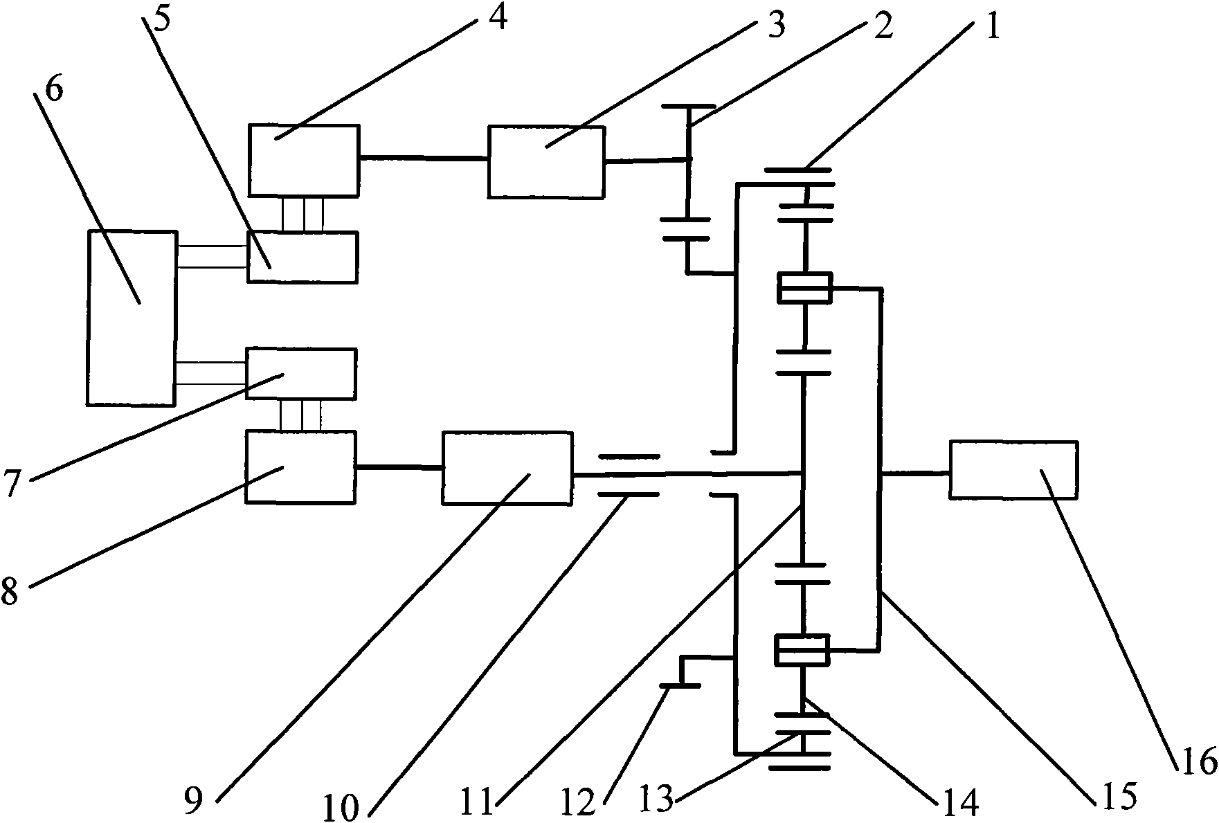
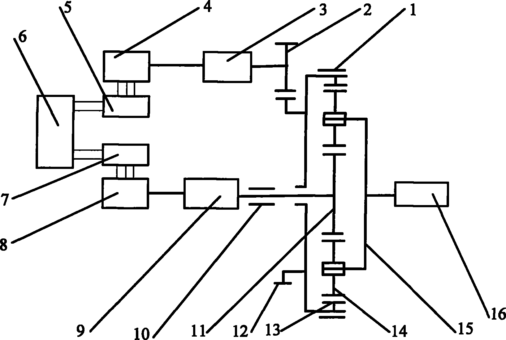
[0009] The present invention is composed of locking device 1, power input gear 2, No. 1 speed reducer 3, No. 1 motor 4, No. 1 controller 5, energy storage device 6, No. 2 controller 7, No. 2 motor 8, and No. 9, locking device 10, sun gear 11, ring gear outer teeth 12, ring gear inner teeth 13, planetary gear 14, planet carrier 15, driving wheel 16, characterized in that: No. 1 motor 4 and No. 2 motor 8 Arranged on the same side, and the shafts are arranged in parallel, the output power of the No. 1 motor 4 passes through the No. 1 reducer 3, the power input gear 2, and the outer gear of the ring gear 12; the output power of the No. 2 motor 8 passes through the No. 2 reducer 9 and the sun gear 11 , through the planetary gear to achieve speed coupling and output to the drive wheel 16 by the planetary carrier 15 .

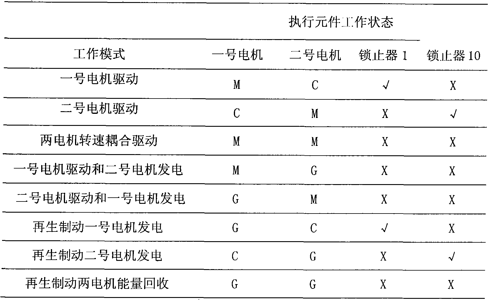
[0010] The No. 1 controller 5 controls the working state and power output of the No. 1 moto...


PUM


Abstract

The invention provides a dual power coupling drive assembly adopting a dual-motor rotating speed coupling drive mode, and the dual power coupling drive assembly can meet the power demands of heavy vehicles in the process of running. In the invention, the rotating speed coupling of a planetary gear is used as the power coupling of a first motor 4 and a second motor 8; the first motor 4 and the second motor 8 are arranged at the same side, and the shafts of the first motor 4 and the second motor 8 are parallel to each other, the power output by the first motor 4 passes through a first speed reducer 3, a power input gear 2 and a gear ring external gear 12, the power output by the second motor 8 passes through a second speed reducer 9 and a sun gear 11, then the rotating speed coupling of the two motors are realized by the planetary gear, and a planet carrier 15 outputs power to a driving wheel 16.

Description

technical field [0001] The invention belongs to the technical field of power assembly components, and in particular relates to a dual-motor power coupling drive assembly. Background technique [0002] It is difficult for a single motor to drive a vehicle to meet the needs of low-speed high-torque and high-speed low-torque at the same time. Therefore, in order to meet the power requirements of the vehicle, a gearbox is often added between the motor and the drive wheels. The existence of the gearbox makes the driving motor in the gearbox. The power loss inside is large, and there is a shift power interruption. Contents of the invention [0003] The purpose of the present invention is to provide a coupling drive assembly suitable for dual-motor rotation speeds to overcome the above-mentioned shortcomings in current single-motor-driven vehicles. The transmission path of the braking torque is shortened, which is beneficial to improving the regenerative braking energy recovery ...

Claims


Application Information

Patent Timeline
IPC IPC(8): B60K1/02B60K17/28B60L7/10
Inventor 孙逢春董玉刚张承宁武小花
Owner BEIJING INSTITUTE OF TECHNOLOGYGY
Learn More