Optical insertion and return loss tester

A tester and insertion return loss technology, applied in the field of circuit modules, can solve the problems of manual calculation, complicated operation of return loss tester, high price, etc., and achieve the effect of fast running speed, small error and low cost

Inactive Publication Date: 2011-07-27
上海光家仪器设备有限公司 +1
View PDF0 Cites 7 Cited by
  • Summary
  • Abstract
  • Description
  • Claims
  • Application Information

AI Technical Summary

Problems solved by technology

The so-called return loss is the ratio of the incident optical power to the reflected optical power after the optical fiber device; the so-called insertion loss is the optical power lost after the light passes through the optical fiber device; it is the difference between the incident optical power and the output optical power; According to the definition of return loss, there are measuring equipment of return loss tester in the market. The operation of return loss tester is complicated, expensive, and can only be used for return loss test; according to the definition of insertion loss, optical power meter can be used and splitter to measure insertion loss, but manual calculation is required, and there is no instrument specially used to measure insertion loss on the market

Method used


Image

  • Optical insertion and return loss tester
  • Optical insertion and return loss tester
  • Optical insertion and return loss tester

Examples


Embodiment Construction

[0010] Below in conjunction with accompanying drawing and specific embodiment the present invention is described in further detail:

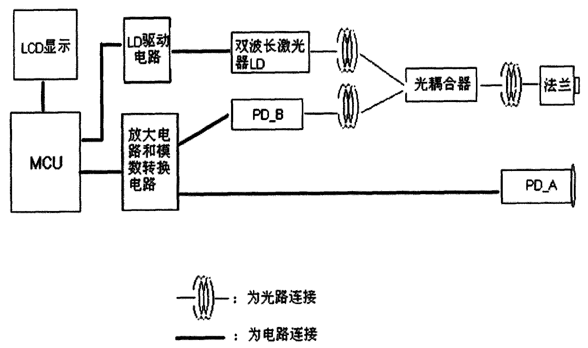
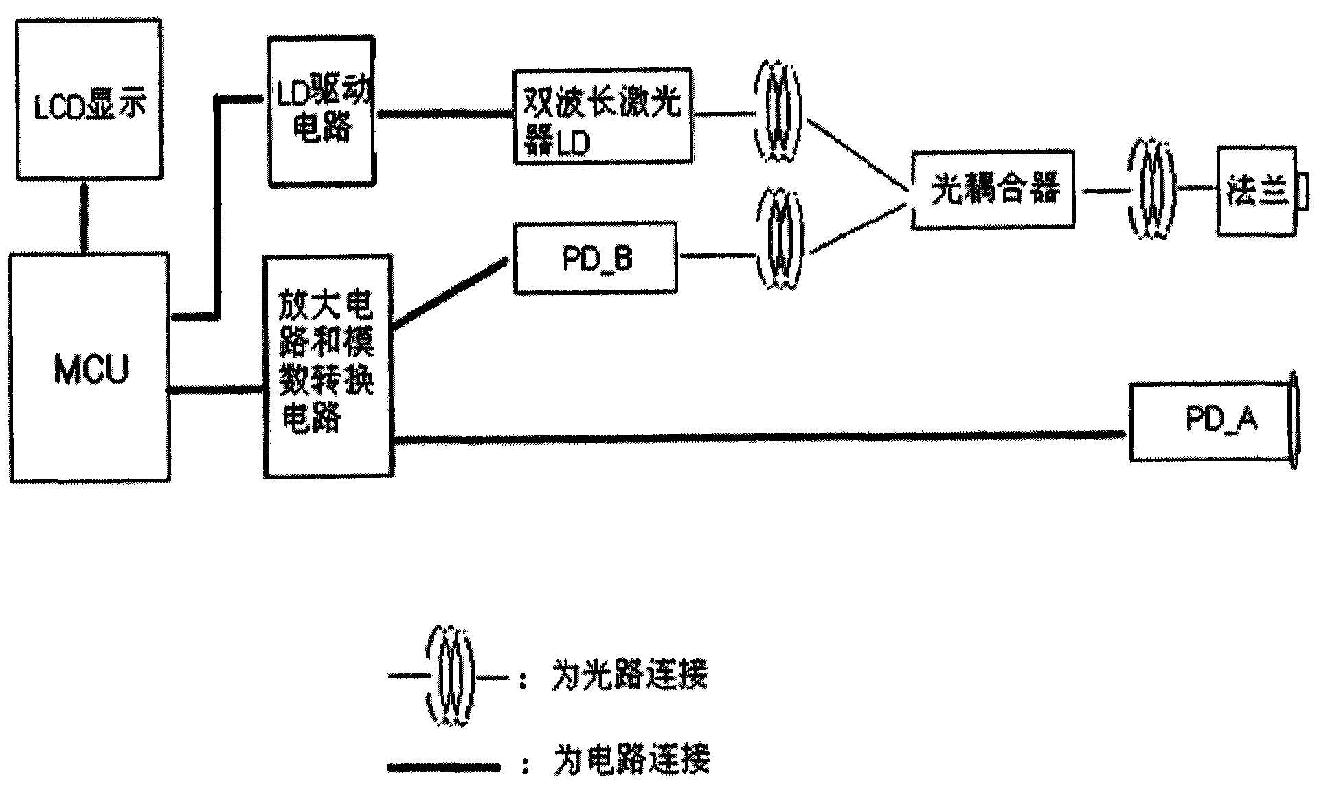
[0011] Depend on figure 1 It can be seen that the present invention includes: a dual-wavelength laser LD; the dual-wavelength laser LD is connected to an optical coupler through an optical path; the optical coupler is connected to a flange through an optical path; the flange is connected to an optical coupler through an optical path; The device is connected with the second detector PD_B through the optical path; the dual-wavelength laser LD is connected with the MCU through the LD drive circuit; the second detector PD_B is connected with the MCU through the amplifier circuit and the analog-to-digital conversion circuit; the amplifier circuit and the analog The digital conversion circuit is also connected with the first detector PD_A;

[0012] The MCU is also connected with the LCD display.

[0013] Flange, optical coupler, two PDs in the prese...


PUM


Abstract

The invention relates to an optical insertion and return loss tester. The tester comprises a dual-wavelength laser, wherein the dual-wavelength laser is connected with an optical coupler through an optical path; the optical coupler is connected with a flange through an optical path; the flange is connected with the optical coupler through an optical path; the optical coupler is connected with a second detector through an optical path; the dual-wavelength laser is connected with a MCU (micro-programmed control unit) through an LD (laser diode) drive circuit; the second detector is connected with the MCU through an amplification circuit and an analog-to-digital conversion circuit; and the amplification circuit and the analog-to-digital conversion circuit are also connected with a first detector. The optical insertion and return loss has the beneficial effects of fast running speed, strong working performance, small errors in test results, simple structure, low cost, intuitive display and small volume and good portability, integrates functions of a plurality of instruments and is convenient to operate.

Description

technical field [0001] The invention relates to an optical measuring instrument, in particular to a circuit module of an optical insertion return loss tester. Background technique [0002] Standing out from optical communication, optical fiber communication technology has become one of the main pillars of modern communication and plays a pivotal role in modern telecommunication networks. As an emerging technology, optical fiber communication has been developing rapidly and widely used in recent years, which is rare in the history of communication. It is also an important symbol of the world's new technology revolution and the main transmission tool for various information in the future information society. [0003] As the transmission medium of light in optical communication, optical fiber, together with optical communication devices, connection devices and other related devices and equipment, constitutes the transmission hub of the entire optical communication network. The...

Claims


Application Information

Patent Timeline
Patent Type & Authority Applications(China)
IPC IPC(8): G01M11/02
Inventor 阮志光陈春
Owner 上海光家仪器设备有限公司
Why Eureka
Try Eureka