Self-heating deicing system of high-tension transmission lines

A technology of high-voltage transmission lines and high-voltage transmission lines, which is applied to the installation of electrical components, cables, and the shape of heating elements, etc., which can solve the problems of high insulation strength between heating cores and transmission cores, and solve capacity limitations and reduce insulation. Requirements, avoiding the effect of heat

Active Publication Date: 2011-07-27
刘启端
View PDF6 Cites 13 Cited by
  • Summary
  • Abstract
  • Description
  • Claims
  • Application Information

AI Technical Summary

Problems solved by technology

[0011] Another problem to be solved by the present invention is to solve the problem that the insulation strength between the heating wire core and the transmission wire core is too high in the existing deicing method, thereby not only ensuring the feasibility of the scheme but also ensuring the deicing Work with good reliability and safety

Method used


Image

  • Self-heating deicing system of high-tension transmission lines
  • Self-heating deicing system of high-tension transmission lines
  • Self-heating deicing system of high-tension transmission lines

Examples


Embodiment 1

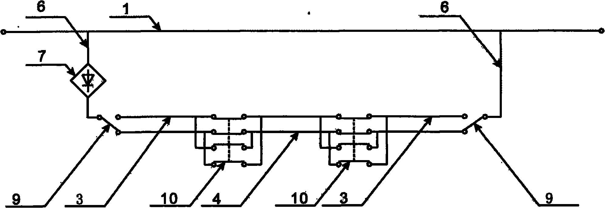
[0037] Such as image 3 As shown, the scheme uses an external DC power supply, and forms a deicing circuit through the transmission line core and the heating line core in the transmission cable, and the two ends of the transmission line core and the heating line core are respectively connected by short-circuit equalizing lines; The power transmission cable is also provided with a bypass core, which is used to control the deicing of the ice-covered section of the line; by switching the switch in the deicing current circuit, the deicing work only needs to Part of the line covered with ice, or in the case that the entire power transmission line has been covered with ice, the de-icing work mode can be used to solve the problem of the capacity limitation of the de-icing power supply.

Embodiment 2

[0039] Such as Figure 4 As shown, the working current of the heating core comes from the DC power provided by the isolated power supply. A power supply device is added in the closed loop between the heating core and the parallel-connected transmission core to form a heating loop on the transmission line to achieve the purpose of melting ice. The primary side coil of the transformer is connected to the main power transmission line, and the secondary side coil of the transformer is connected to the rectifier device to provide deicing power for the deicing circuit. The purpose of segmented deicing can also be achieved by connecting a switch with address programming or remote control function in parallel.

Embodiment 3

[0041] Such as Figure 5 As shown, in this scheme, a variable impedance is connected in series in the main power transmission line to realize the shunting of the power current in the main power transmission line to the deicing circuit, so as to provide power for the deicing circuit.


PUM


Abstract

The invention discloses a self-heating deicing system of high-tension transmission lines. The self-heating deicing system is characterized in that the system comprises a high-tension transmission cable and a deicing power module; a transmission cable core and a heating cable core are arranged inside the high-tension transmission cable; the heating cable core is connected with two ends of the transmission cable core through pup joint equalizers; the deicing power module adopts an external direct current power source or a power module directly led out from a high-tension transmission line; and the deicing power module is connected with the transmission cable core and the heating cable core inside the high-tension transmission cable and the pup joint equalizers through a change-over switch to form a heating circuit in the high-tension transmission cable. The self-heating deicing system can realize the deicing operation to the high-tension transmission cable in ice coating sections by building the self-heating deicing circuit in the high-tension transmission cable under the condition of uninterruptible power supply; and moreover, the self-heating deicing system can be matched with the existing high-tension transmission power monitoring system to realize the sectionalized and time-shared deicing to ice coating lines in an automation control manner according to the ice coating situation of lines.

Description

technical field [0001] The invention relates to the technical field of power system safety, in particular to a self-heating deicing system for high-voltage transmission lines. Background technique [0002] In the high-voltage transmission system, the transmission line is erected for a long distance, and when a freezing rain disaster occurs, a large area is often affected. At this time, manual and various mechanical deicing work is limited by the working surface and the harsh working environment. , resulting in low efficiency, high cost and long construction period, which is not conducive to promotion and implementation. The method of current heating and deicing is an important solution. In the power outage deicing scheme, because all the electric energy required for deicing work needs to be provided separately, there are high requirements for the total energy required by the power supply and the total output power, and the power failure of large-scale transmission lines has...

Claims


Application Information

Patent Timeline
Patent Type & Authority Applications(China)
IPC IPC(8): H02G7/16H05B3/56
Inventor 刘启端
Owner 刘启端
Why Eureka
Try Eureka