
Vascular stent cutting device and vascular stent cutting method

A vascular stent and cutting equipment technology, applied in welding equipment, laser welding equipment, metal processing equipment and other directions, can solve the problems of backward technology, insufficient miniaturization of the system, high cost, and achieve the effect of low cost and great practical application value

Inactive Publication Date: 2011-08-03
BEIJING UNIVERSITY OF CIVIL ENGINEERING AND ARCHITECTURE
View PDF11 Cites 40 Cited by
  • Summary
  • Abstract
  • Description
  • Claims
  • Application Information

AI Technical Summary

Problems solved by technology

Most of the existing vascular stent cutting equipment uses Nd:YAG laser, which has defects such as short lamp life, low conversion efficiency, large energy consumption, insufficient miniaturization of the system, low precision, slow cutting, large heat-affected zone, and high production cost.
[0005] The development of vascular stent processing in China is relatively late, the technology is relatively backward, and there is a big gap between the processing accuracy and quality compared with foreign countries. Medical vascular stents mainly rely on imports, and the high cost is beyond the reach of the general public. How to develop a vascular stent processing The ability of equipment to process low-cost, high-precision and high-quality vascular stents is a major issue facing Chinese researchers

Method used


Image

  • Vascular stent cutting device and vascular stent cutting method
  • Vascular stent cutting device and vascular stent cutting method
  • Vascular stent cutting device and vascular stent cutting method

Examples


Embodiment Construction

[0030] The following examples can enable those skilled in the art to understand the present invention more comprehensively, but do not limit the present invention in any way.

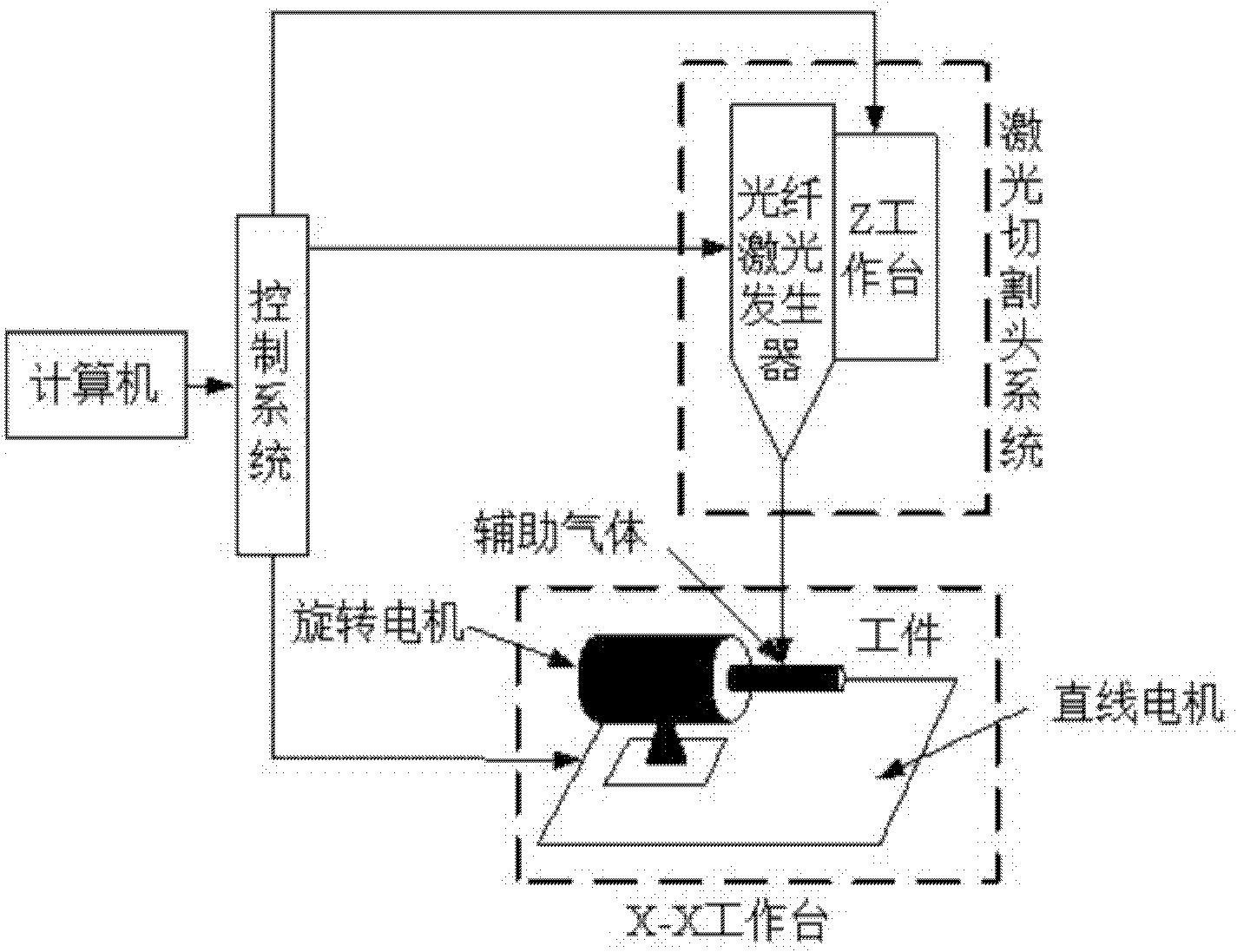
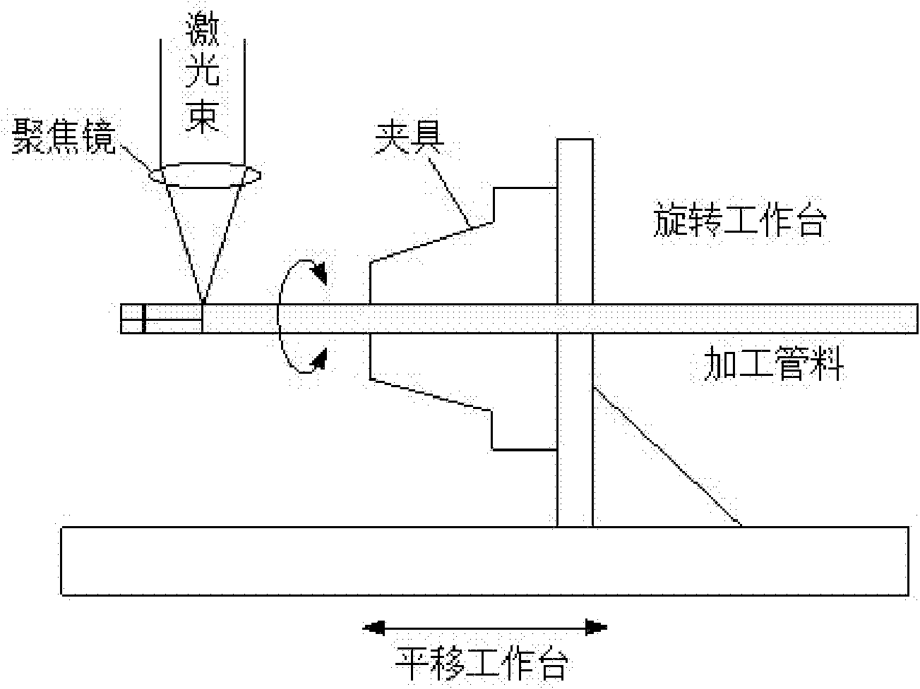
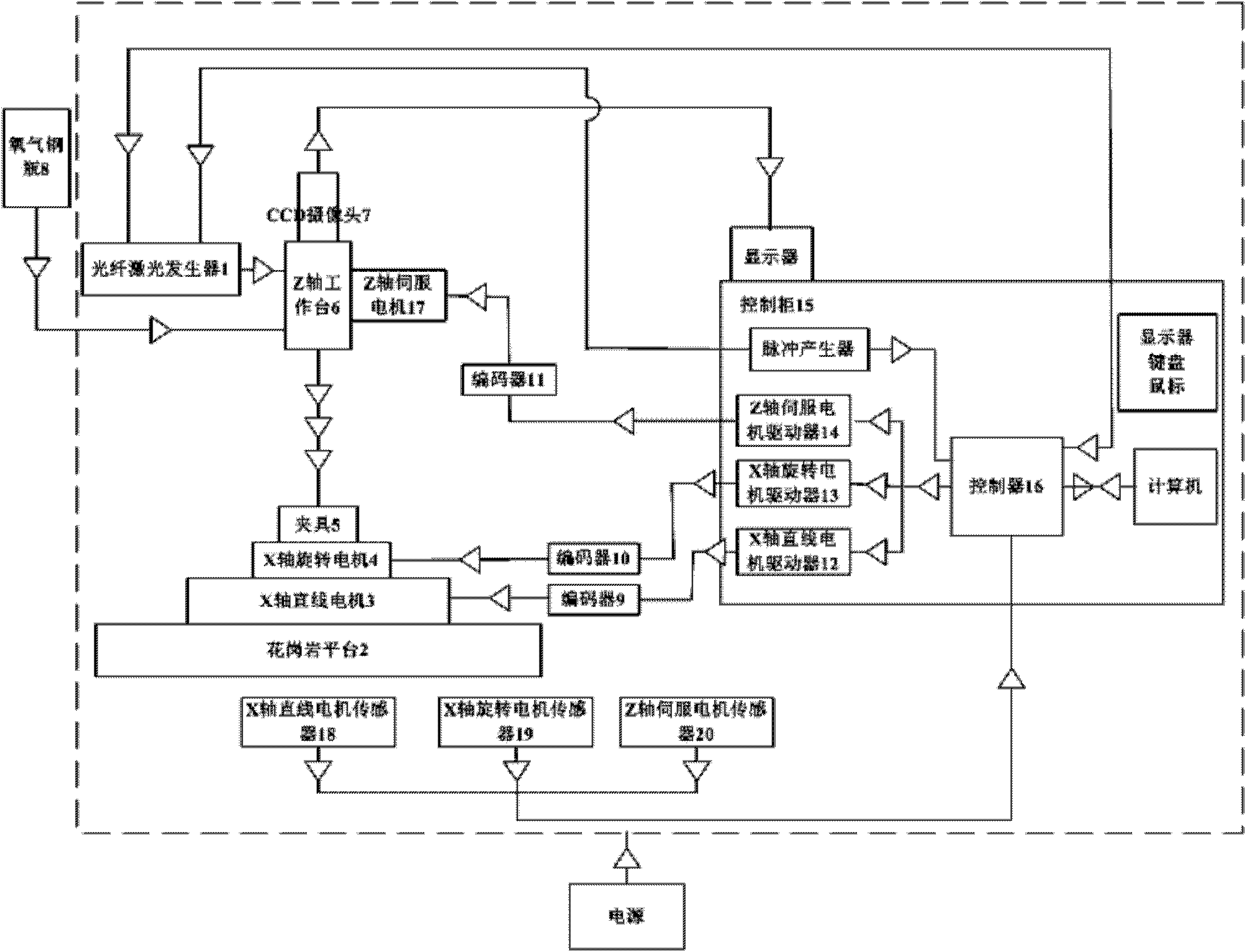
[0031] Fiber laser cutting equipment for vascular stents as shown in the accompanying drawings, including a laser cutting head system, an X-X table that can move horizontally along the X-axis and rotate around the X-axis and a granite platform with counterweight 2, the workpiece set on the rotating motor Fixture 5, the laser cutting head system includes a fiber laser generator 1, a Z table 6 that can move in the vertical direction, and the Z table 6 is a motion platform that is composed of a Z-axis servo motor 17 that can move in the vertical direction, so The laser generator 1 is installed on the Z workbench 6; the laser generator moves together with the Z workbench, and also includes a motion control part, a laser generator control part and a system controller provided with the X-X workbench and the Z ...


PUM


Abstract

The invention discloses a vascular stent cutting device and a vascular stent cutting method, belonging to the technical field of medical apparatus processing equipment. The vascular stent cutting device comprises an X-X workbench, a platform, a laser cutting head system and a control system, wherein the X-X workbench is a two-dimensional movement feeding platform which is composed of an X-axis linear motor capable of horizontally moving along the X-axis and an X-axis rotating motor capable of rotating around the X-axis; the X-axis rotating motor is provided with a workpiece fixture; the platform is in counter weight with the X-X workbench; the laser cutting head system comprises a laser generator and a Z workbench; and the Z workbench is a moving platform which is composed of a Z-axis servo motor capable of moving along the vertical direction. A processing and cutting device for producing a vascular stent provided by the invention realizes that the production efficiency of the vascular stent is high, and the production cost of the vascular stent is low, so as to conveniently and effectively process the vascular stents with various shapes. The vascular stent cutting device solves the problems existing in a vascular stent processing device that the miniaturization is not enough, the processing precision is not high, the cutting is slow, the heat affected zone is larger, the service life is short, the production cost is high, etc.

Description

technical field [0001] The invention belongs to the technical field of medical device processing equipment, in particular to the field of micromachining of brackets of different materials and tubular thin-walled materials, and specifically relates to a cutting equipment and method for a blood vessel bracket. Background technique [0002] At present, the effectiveness and safety of vascular stent technology in the treatment of vascular stenosis have been widely recognized in clinical applications, and it has become a new treatment technology, forming a broad market demand. Some large medical device companies in the world have launched their own vascular stent products, such as Cordis, Medtronic, Boston, Scientific and Guidant, etc. The stent products of these large companies occupy most of the international market. Domestic companies such as Minimally Invasive Medical Devices (Shanghai) Co., Ltd. have independently developed the Mustang coronary stent and the Firebird drug st...

Claims


Application Information

Patent Timeline
IPC IPC(8): B23K26/36B23K26/08B23K26/06B23K26/14B23K26/142B23K26/38
Inventor 杨建伟杜艳平任思周明张惠刚姚德臣
Owner BEIJING UNIVERSITY OF CIVIL ENGINEERING AND ARCHITECTURE
Learn More