Error matrix compensation method of monopulse tracking receiver system
A technology for tracking receivers and system errors, applied to transmission systems, electrical components, etc., can solve problems such as large cross-coupling, failure to track targets, and poor tracking effects
- Summary
- Abstract
- Description
- Claims
- Application Information
AI Technical Summary
Problems solved by technology
Method used
Image
Examples
Embodiment Construction
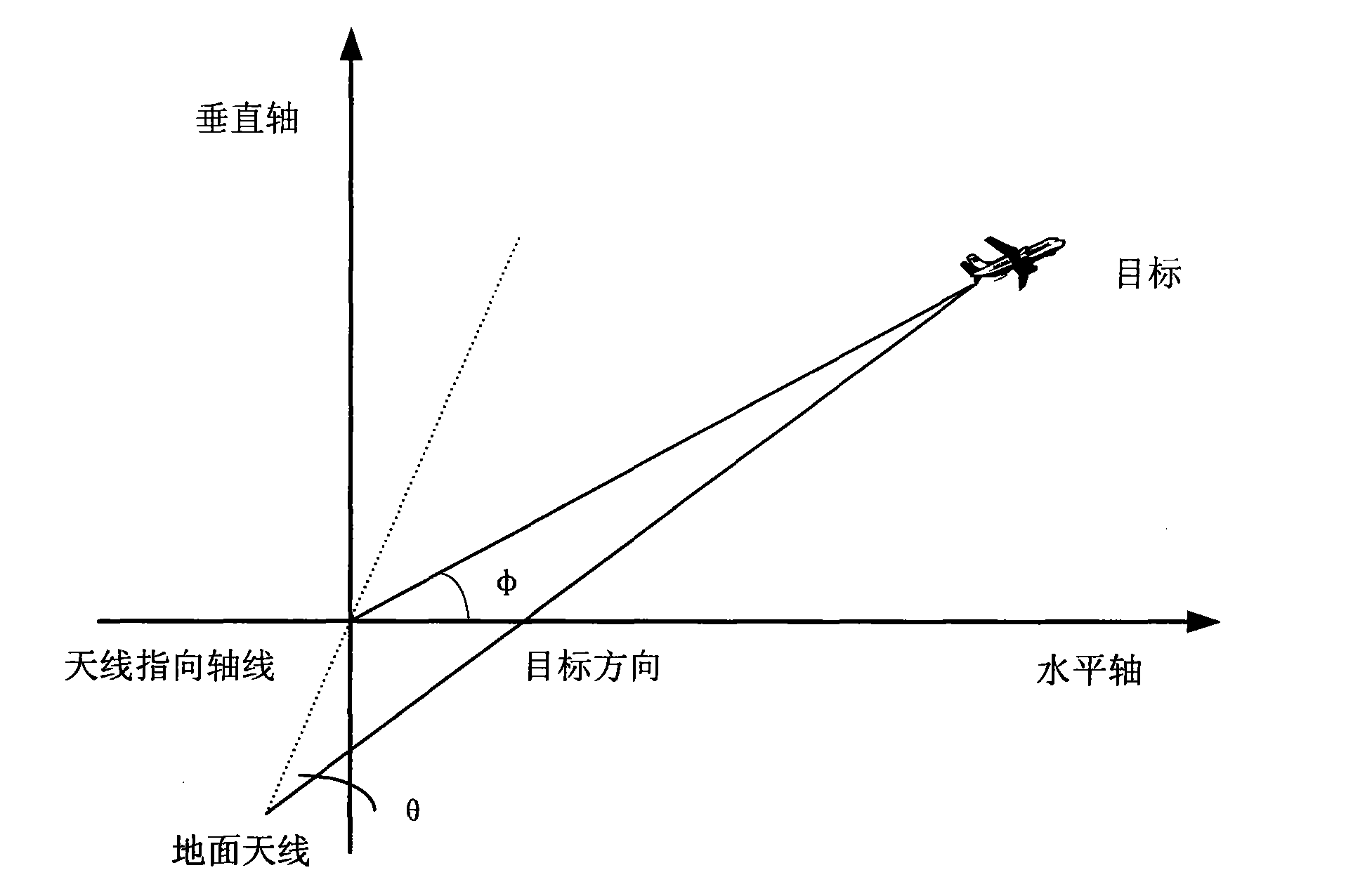
[0051] figure 1 is a schematic diagram of the relationship between the ground tracking antenna pointing and the relative position of the target.
[0052] The present invention comprises steps:
[0053] ① Deduce the specific mathematical expression of the compensation matrix;
[0054] The relationship between the ground tracking antenna and the target is shown in the accompanying drawing (1) of the specification. For the two-dimensional tracking antennas of the TE11 mode and TE21 mode, regardless of the influence of the system error, the sum and difference branch signals are respectively expressed as:
[0055]
[0056]
[0057] where S ∑ (t)-Helu signal; E Δ (t)-angle error signal; D(t), is the orthogonal low-frequency square wave; μ is the normalized difference slope; θ is the angle between the aircraft and the antenna axis; K is the antenna and signal amplitude; W c (t) is the carrier signal; θ(t) is the modulation signal; is the angle between the projection of th...
PUM
 Abstract
Description
Claims
Application Information
 - R&D
- Intellectual Property
- Life Sciences
- Materials
- Tech Scout
- Unparalleled Data Quality
- Higher Quality Content
- 60% Fewer Hallucinations
Browse by: Latest US Patents, China's latest patents, Technical Efficacy Thesaurus, Application Domain, Technology Topic, Popular Technical Reports.
© 2025 PatSnap. All rights reserved.Legal|Privacy policy|Modern Slavery Act Transparency Statement|Sitemap|About US| Contact US: help@patsnap.com


