Distributed optical fiber temperature sensing measurement device and method

A distributed optical fiber and temperature measurement technology, applied in measuring devices, thermometers, measuring heat, etc., can solve problems such as inaccurate temperature monitoring, delayed fire response time, inaccurate location of ignition point, etc., to achieve accurate online temperature measurement, temperature Ease of calibration and improved reliability

Active Publication Date: 2011-08-10
PINGHU BOHUI COMM TECH
View PDF7 Cites 23 Cited by
  • Summary
  • Abstract
  • Description
  • Claims
  • Application Information

AI Technical Summary

Problems solved by technology

However, since the sensing optical cables are all installed outdoors, such as distributed optical fiber temperature sensing devices used in traffic tunnels, the sensing optical cables are laid at a distance of about 100mm from the tunnel vault, and the height from the ground is close to 7m, so it is not easy to heat it calibration
Moreover, the conventional water bath calibration method cannot perform real-time online calibration, which affects the reliability of the distributed optical fiber temperature sensing device
[0006] In addition, for some applications, for example, some special or critical parts require higher temperature measurement accuracy (short heating area), or need to improve the response time of temperature measurement, only the distributed temperature measurement function cannot meet the application requirements:
[0007] For example, in the field of power applications, it is necessary to monitor high-voltage cables and switch cabinets at the same time; when monitoring overheating of linear high-voltage cables, the use of distributed temperature measurement can effectively avoid measurement blind spots, thereby realizing complete monitoring of high-voltage cables; The temperature monitoring of high-voltage switchgear is mainly to monitor the temperature at the busbar and contacts inside the switchgear. The area to be tested is relatively small, and it is inconvenient to lay sensing optical cables in the area to be tested, and the traditional distributed optical fiber temperature sensor The temperature measurement accuracy of the system is limited by the spatial resolution, and the temperature monitoring of small monitoring points in the area to be measured is inaccurate;
[0008] As another example, for a long-distance highway traffic tunnel, the use of a distributed optical fiber temperature sensing system can achieve comprehensive monitoring of the fire in the measurement area; Drift will occur, and the temperature response time of the sensing cable will lag behind, causing the system to obtain the position of the ignition point after the drift of the hot spot; making the system's positioning of the ignition point inaccurate, unable to reflect the temperature change in the monitoring area in time, and delaying the detection of the fire. Response time affects the accuracy and timeliness of temperature measurement

Method used


Image

  • Distributed optical fiber temperature sensing measurement device and method
  • Distributed optical fiber temperature sensing measurement device and method
  • Distributed optical fiber temperature sensing measurement device and method

Examples


Embodiment 1

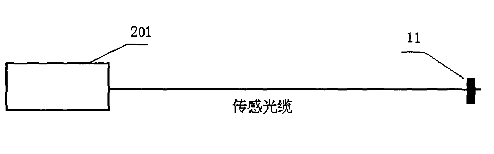
[0056] see figure 1, a distributed optical fiber temperature sensing measurement device, including a measurement host 201, a sensing optical cable and a temperature sensor 11; in this embodiment, the distributed temperature measurement is based on spontaneous Raman scattering effect and optical time domain reflection OTDR technology, sensing The length of the optical cable is 2km; the point temperature sensor 11 is a fiber grating temperature sensor installed on the sensing optical cable;

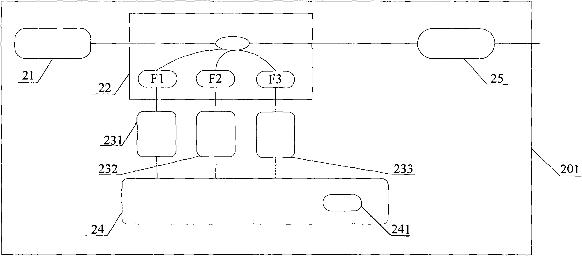
[0057] see figure 2 , the measurement host 201 includes a laser 21, a spectroscopic module 22, a detection module, an analysis unit 24 and a reference fiber box 25;

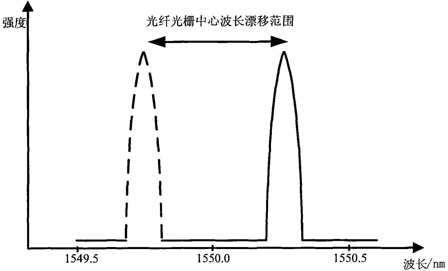
[0058] The laser 21 is a wavelength-scanning laser; the central wavelength of the laser is 1549.5nm when the driving current is 800mA; the scanning of the central wavelength of the laser can be realized by adjusting the driving current of the laser or the operating temperature of the laser; in this embodiment, adjusting the ...

Embodiment 2

[0092] A distributed optical fiber temperature sensing measuring device, different from the measuring device described in embodiment 1 is:

[0093] 1. The measurement device of this embodiment does not include the reference fiber box 25 .

[0094] 2. The optical filter F2 in the optical splitting module filters out the Rayleigh light transmitted along the sensing optical cable to be received by the detector 232 .

[0095] This embodiment also provides a distributed optical fiber temperature sensing measurement method, which is different from the measurement method described in Embodiment 1 in that:

[0096] 1. In step B1, perform point temperature measurement to obtain the precise ambient temperature T(L) at the position where the fiber grating is located;

[0097] 2. In step B2, distributed temperature measurement is carried out to obtain Stokes light and Rayleigh light signals at each measurement point along the sensing optical cable laying area. The ratio of these two sign...

Embodiment 3

[0106] see Figure 4 , a distributed optical fiber temperature sensing measuring device, different from the measuring device described in embodiment 1 is:

[0107] The measurement device also includes a calibration module 26, and the detection module also includes a detector 234. The calibration module 26 is connected to the spectroscopic module 22 and the detector 234 respectively, and is used to calibrate the wavelength of the laser 21, and then accurately calibrate the central wavelength of the temperature sensor 11. The drift amount; the detector 234 is an InGaAs PIN detector, which is connected with the calibration module 26 and the analysis unit 24;

[0108] The calibration module 26 can be a gas absorption box or a Fabry-Perot etalon or a reference fiber grating of known wavelength or a combination thereof; the present embodiment adopts H 13 CN gas absorption box;

[0109] h 13 CN gas has different characteristic absorption peaks around 1550nm, among which, the wavel...


PUM

PropertyMeasurementUnit
lengthaaaaaaaaaa
currentaaaaaaaaaa
wavelengthaaaaaaaaaa

Abstract

The invention relates to a distributed optical fiber temperature sensing measurement device which comprises a measuring host machine and a sensing optical cable, wherein the measuring host machine comprises a laser, a light split module, a detection module and an analysis unit; the device is characterized in that the sensing optical cable is provided with a temperature sensor; the light split module is used for respectively filtering out scattered lights transmitted along the sensing optical cable and reflected lights/transmitted lights of the temperature sensor and transmitting the scattered lights and the reflected lights/transmitted lights to the analysis unit by the detection module; and the analysis unit is used for obtaining distributed temperature measuring data according to the information of the scattered lights and obtaining dot-type temperature measuring data according to the information of the scattered lights and the reflected lights. The invention also provides a distributed optical temperature sensing measurement method. The device and the method combine the distributed measurement function and the dot-type measurement function, can also carry out on-line temperature correction and have the advantages of simple structure, low cost and the like.

Description

technical field [0001] The invention relates to an optical fiber temperature sensing and measuring device and method, in particular to a distributed optical fiber temperature sensing and measuring device and method with a point temperature measuring function. Background technique [0002] Distributed optical fiber temperature sensing system is a new real-time and distributed measurement system based on OTDR technology and Raman scattering technology. Distributed optical fiber temperature sensing devices have been widely used in highway traffic tunnels, high-voltage cable trenches, subways and other fields. [0003] At present, a widely used distributed optical fiber temperature sensing device includes a light source module, a light splitting module, a detection module, a reference unit and a sensing optical cable. The reference unit includes a section of reference optical fiber. The temperature of the reference optical fiber can be constant or measured in real time; the ref...

Claims


Application Information

Patent Timeline
Patent Type & Authority Applications(China)
IPC IPC(8): G01K11/32G01K11/3206G01K11/322G01K11/324
Inventor 涂勤昌张艳辉
Owner PINGHU BOHUI COMM TECH
Why Eureka
Try Eureka