Al technical title is built by PatSnap Al team. It summarizes the technical point description of the patent document.
A processing method and inner hole technology are applied in the field of metal parts processing and manufacturing to achieve the effect of reducing processing costs
Inactive Publication Date: 2011-08-17
LIUZHOU SHUANGJI MACHINERY
View PDF4 Cites 24 Cited by
Summary
Abstract
Description
Claims
Application Information
AI Technical Summary
This helps you quickly interpret patents by identifying the three key elements:
Problems solved by technology
Method used
Benefits of technology
Problems solved by technology
[0003] The problem to be solved by the invention is to provide a processing method for the inner hole of the cylinder, which can solve the problems of the existing inner hole of the cylinder. The processing method has high scrap rate and high processing cost
Method used
Image
Click on the blue label to locate the original text in one second.
Reading with bidirectional positioning of images and text.
Examples
Embodiment 1
[0024] Embodiment 1: A process for manufacturing a dump truck lift cylinder with a bore of 200 mm, a stroke of 1000 mm, and a pressure of 16 MPa.
[0025] 1. Preparation of materials: Select No. 45 carbon seamless steel pipe with an outer diameter of 232 mm and a thickness of 18 mm as the raw material, and cut the seamless steel pipe into cylinder blanks with a length of 1000 mm according to the design requirements;
[0026] 2. Pretreatment: Carry out quenching and tempering treatment on the cylinder blank and straighten it to ensure that the hardness of the cylinder blank is HRC28~32, and the bending is not more than 3 mm; the two ends of the pretreated cylinder blank are turned out of the boring hole Position the spigot by process, and weld the external components of the cylinder body;
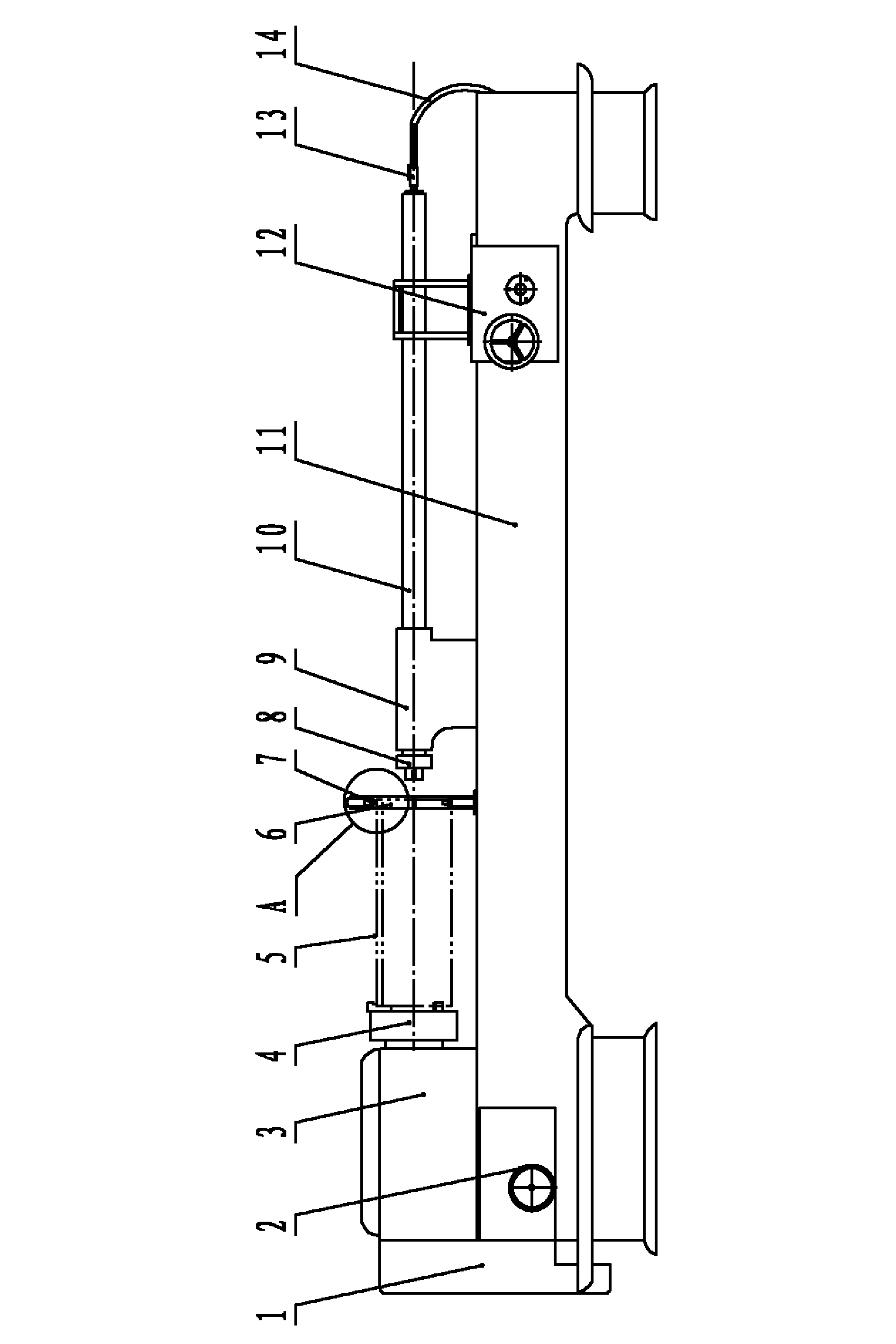
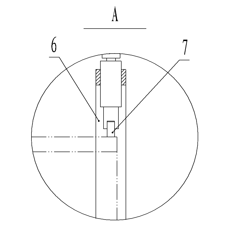
[0027] 3. Rough boring: The inner hole of the rough boring is processed on a special machine tool, and one end of the cylinder blank is clamped on the chuck of the special machine to...
Embodiment 2
[0033] Embodiment 2: A process for manufacturing a dump truck lift cylinder with a bore of 160 mm, a stroke of 1000 mm, and a pressure of 16 MPa.
[0034] In this embodiment, except that the processing parameters of rough boring, fine boring and rolling processing are different from those of embodiment 1, other parts are the same as those of the above-mentioned embodiment 1, and the processing parameters of rough boring, fine boring and rolling processing are:
[0035] Rough boring: cutting speed 80 m / min, cutting depth 2 mm, feed rate 0.5 mm / rev;
[0036] Fine boring: cutting speed 100 m / min, cutting depth 0.5 mm, feed rate 1.3 mm / rev;
[0037] Rolling: The radius of the transition circle between the cylindrical surface of the roller and the two end faces is 3.5 mm; the rolling speed is 100 m / min; the rolling depth is 0.1 mm; the feed rate is 1.3 mm / rev .
PUM
Property
Measurement
Unit
thickness
aaaaa
aaaaa
fatigue bending times
aaaaa
aaaaa
Abstract
The invention discloses a processing method for an inner hole of a cylinder. After being finely bored, the inner hole of the cylinder is rolled; the coarse boring, fine boring, and rolling of the processing method are all implemented by a special machine tool manufactured by configuring an engine lathe; a guide tail seat of the machine tool is arranged between a chuck and a slide carriage; the upper surface of the slide carriage is fixedly connected with a boring rod penetrating through a through hole of the guide tail seat; a cylinder bracket is arranged between the guide tail seat and the chuck; a roller is arranged at the support end of the cylinder bracket and used for supporting and locating the other end of the cylinder; a cylinder is adopted as a running pulley of a rolling head, and the cylindrical surface and the two end surfaces of the running pulley are in smooth transition; a bearing body is connected with an outer thread of the boring rod through an inner thread; a conical cylinder is adopted as the outer side surface of the bearing body; and a limiting pin is arranged between the bearing body and the boring rod. Compared with the prior art, the processing method for the inner hole of the cylinder can solve the problems of high rejection ratio and high processing cost of a current processing method for the inner hole of the cylinder.
Description
technical field [0001] The invention relates to the technical field of processing and manufacturing of metal parts, in particular to a method for manufacturing and processing a cylinder and similar workpieces in a cylinder with a large length-to-diameter ratio. Background technique [0002] The inner hole of cylinder parts is generally relatively large in length and diameter, the wall of the cylinder is thin, and the precision and surface roughness of the inner hole are very high. The seamless steel pipe is used as the raw material, and the material is prepared first, that is, the steel pipe is cut into a cylinder body of the required length → cylinder body pretreatment, that is, straightening, quenching and tempering treatment → boring at both ends of the car with process positioning seam and external weld seam → Welding the external components of the cylinder block → Rough boring inner hole → Fine boring inner hole → Fine honing. The boring method wherein is usually that...
Claims
Application Information
Patent Timeline
Application Date:The date an application was filed.
Publication Date:The date a patent or application was officially published.
First Publication Date:The earliest publication date of a patent with the same application number.
Issue Date:Publication date of the patent grant document.
PCT Entry Date:The Entry date of PCT National Phase.
Estimated Expiry Date:The statutory expiry date of a patent right according to the Patent Law, and it is the longest term of protection that the patent right can achieve without the termination of the patent right due to other reasons(Term extension factor has been taken into account ).
Invalid Date:Actual expiry date is based on effective date or publication date of legal transaction data of invalid patent.