
Pneumatic ejector for carrier-based airplanes of airplane carrier

A carrier-based aircraft and catapult technology, applied in the direction of launching/dragging transmission devices, etc., can solve the problems of many operators, power cannot be adjusted, air tightness reduction, etc., and achieve high power conversion rate, power can be adjusted, and service life long effect

Inactive Publication Date: 2014-04-16
张俊燕
View PDF4 Cites 0 Cited by
  • Summary
  • Abstract
  • Description
  • Claims
  • Application Information

AI Technical Summary

Problems solved by technology

[0003] The deficiencies that the steam catapult of prior art exists are 1) complex structure, high cost
The steam catapult in the United States adopts a parallel design of double slotted cylinders. The high temperature and high pressure steam only acts on two pistons with a diameter of 457mm. Only 4-6% of this steam is converted into the ejection power of the piston, and this 4% of the power is converted during the formation of the first ten meters of the piston, and the remaining 2% of the power is converted by the piston during the remaining 90 meters of travel. Inertial movement, if ejection is carried out at the minimum interval, it needs to consume 20% of the steam of the aircraft carrier boiler; 4) the complexity of the system will inevitably bring more operators, and a catapult requires about 120 operators and repair personnel
The four catapults require more than 500 operators and maintenance personnel, accounting for about 10% of the entire ship's establishment, and the amount of maintenance is large. The flight needs to be grounded after 400 to 500 ejections, and the ship's personnel will perform 1-2 days of maintenance); 5) The ejection power is high, and the power cannot be adjusted, so small aircraft (such as drones) cannot be ejected...
6) The fatal disadvantage is the use of slotted cylinder, the piston is directly linked with the shuttle through the slot, causing the cylinder to be easily deformed, and the slot needs special metal sealing strips to seal, the air tightness is reduced, the loss of steam is large, and the metal sealing strip is easy to Damage directly affects the service life of the ejection cylinder

Method used


Image

  • Pneumatic ejector for carrier-based airplanes of airplane carrier
  • Pneumatic ejector for carrier-based airplanes of airplane carrier
  • Pneumatic ejector for carrier-based airplanes of airplane carrier

Examples


Embodiment

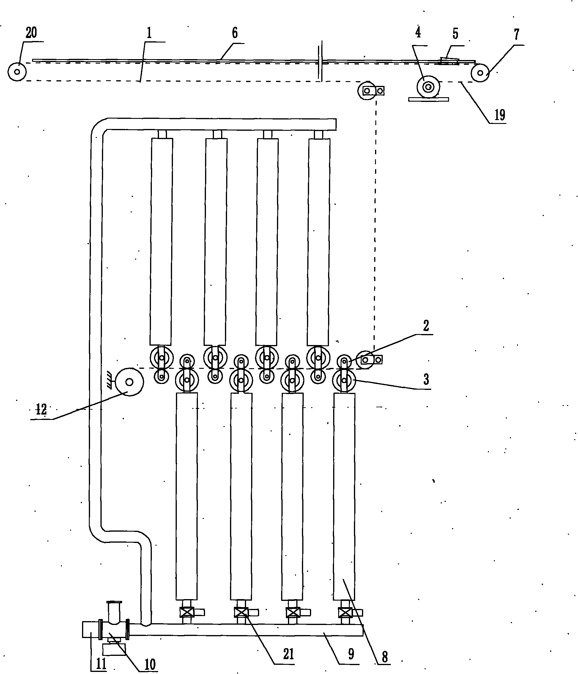
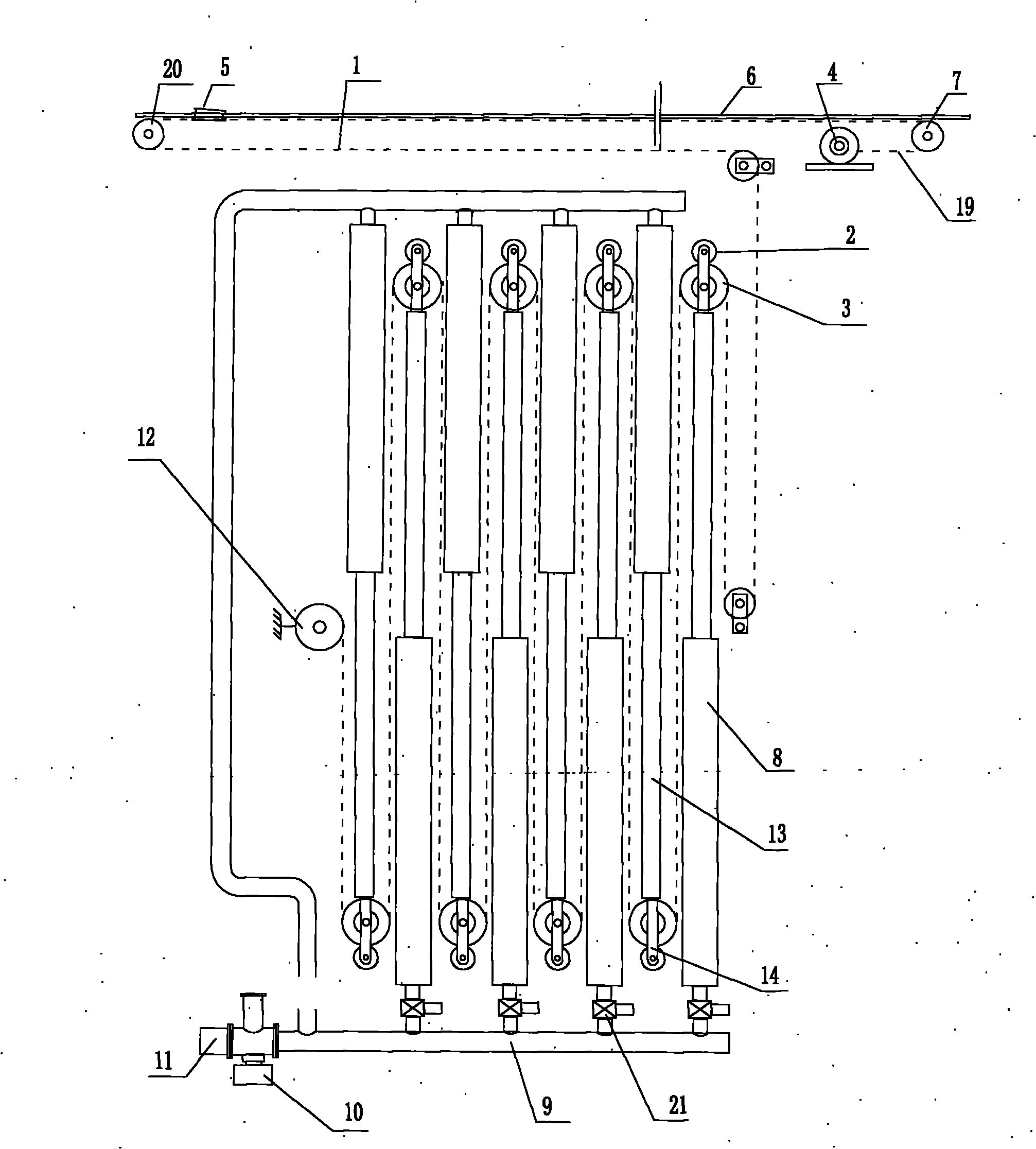
[0033] The ejection steps of the pneumatic carrier aircraft catapult of the present invention are as follows:

[0034] 1) The piston connecting rod is fully retracted into the cylinder body of the pneumatic cylinder, the wire rope is less bent, the homing winch is released, the shuttle is located at the take-off starting point of the take-off runway, and the shuttle is hooked to the ejected aircraft to take off and stand by;

[0035] 2) When the take-off command is issued, the three-way valve is opened, and the high-pressure air source inflates the high-pressure air pipe through the three-way valve, and the high-pressure air pipe inflates each air cylinder respectively. The driving pulley at the end pushes the wire rope to bend, and the wire rope is arranged in an S-shape between the air cylinders. Due to the S-shape bending of the wire rope, the length of the wire rope on the take-off runway is shortened, so the traction shuttle travels from the start point to the end point of...


PUM


Abstract

The invention provides a pneumatic type ejector for carrier-based airplanes of an airplane carrier. A group of steel wire ropes are driven to shrink by a plurality of closed pneumatic cylinders at the same time, and a sliding shuttle on a takeoff runway is driven to slide through the shrinkage of the steel wire ropes, so that the carrier-based airplanes are pushed to take off in an ejecting mode. The structure comprises the carrier-based airplane takeoff runway, the sliding shuttle, the traction steel wire ropes, a plurality of pneumatic cylinder module components, high-pressure gas pipes and a resetting winch, wherein the pneumatic cylinder module components consist of fixed frameworks, the pneumatic cylinders, pistons, piston connecting rods, pulley frames, driving pulleys, anti-breaking pulleys and sliders; the cylinder bodies of the pneumatic cylinders are fixed in the fixed frameworks; the head parts of the pneumatic cylinders are arranged at intervals in a staggered and opposite mode; and the tail parts of the pneumatic cylinders are connected with the high-pressure gas pipes by electrically-controlled valves. Compared with the prior art, the large-thrust multiple acceleration type pneumatic ejector for the carrier-based airplanes of the airplane carrier is characterized in that: the large-thrust multiple acceleration type pneumatic ejector has a simple structure, low cost, light weight, a high power conversion rate and long service life, saves energy and can adapt to the launch of various carrier-based airplanes (including light aircrafts and unmanned aerial vehicles), and the power and the takeoff distance can be adjusted.

Description

technical field [0001] The invention relates to supporting equipment for an aircraft carrier, in particular to a pneumatic catapult for an aircraft carrier. Background technique [0002] As we all know, the most advanced carrier-based aircraft take-off method is steam catapult take-off. It can eject large-scale fixed-wing aircraft (such as early warning aircraft and anti-submarine aircraft) from the flight deck of an aircraft carrier, while the ski-jump deck cannot allow large aircraft such as early warning aircraft and anti-submarine aircraft to take off. The carrier-based aircraft steam catapult is a patent purchased by the United States from the United Kingdom and implemented for aircraft carriers. Currently, only the United States can produce it. The technical indicators of the American aircraft carrier-based steam catapult are that the length of the open cylinder is 70-98 meters, and the diameter of the piston is 475 mm, steam pressure about 20 kg, and each set sells f...

Claims


Application Information

Patent Timeline
Patent Type & Authority Patents(China)
IPC IPC(8): B64F1/06
Inventor 姜明陈罘杲陈卫国霍刚刘俊岭姜鹏朱惠芬
Owner 张俊燕
Learn More