
Single-piston three-cavity pneumatic reset type brake and implementation method thereof

A brake and single-piston technology, applied in the direction of brake types, brake actuators, engine components, etc., can solve the problems that affect the start-up speed and automatic start-up success rate of the unit, the unit cannot be connected to the grid for power generation, and the brake cannot be reset. The effect of value enhancement, simple structure and ingenious design

Active Publication Date: 2012-10-03
DADU RIVER HYDROPOWER DEV
View PDF0 Cites 0 Cited by
  • Summary
  • Abstract
  • Description
  • Claims
  • Application Information

AI Technical Summary

Problems solved by technology

The existing single-piston double-cavity pneumatic return brake mainly has the following problems or defects: the single-piston double-chamber pneumatic return brake generally adopts a circular sealing ring, and the circular sealing ring is easily squeezed and worn due to long-term extrusion. It reduces its sealing performance, which in turn leads to air leakage between the upper and lower chambers of the brake
During the start-up process of the unit, when the upper chamber of the brake is connected to the compressed air and the lower chamber is connected to the exhaust pipe, some compressed air from the upper chamber of the brake with poor sealing performance will flow into the lower chamber, which is affected by the exhaust capacity of the long pipeline system. Especially due to the limitation of the diameter of the automatic control solenoid valve, there will inevitably be a certain residual pressure in the lower chamber, and because the circular area of ​​the lower chamber is much larger than the annular area of ​​the upper chamber (generally 2 to 3 times), it acts on The pressure at the lower end of the piston will be equal to or even slightly greater than the pressure acting on the upper end. In addition, due to the influence of frictional resistance, some or even all of the brakes will not be able to reset
This problem will directly affect the start-up speed of the unit and the success rate of automatic start-up, resulting in the inability of the standby unit to be connected to the grid for power generation in time according to the system requirements

Method used


Image

  • Single-piston three-cavity pneumatic reset type brake and implementation method thereof
  • Single-piston three-cavity pneumatic reset type brake and implementation method thereof
  • Single-piston three-cavity pneumatic reset type brake and implementation method thereof

Examples


Embodiment

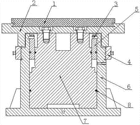
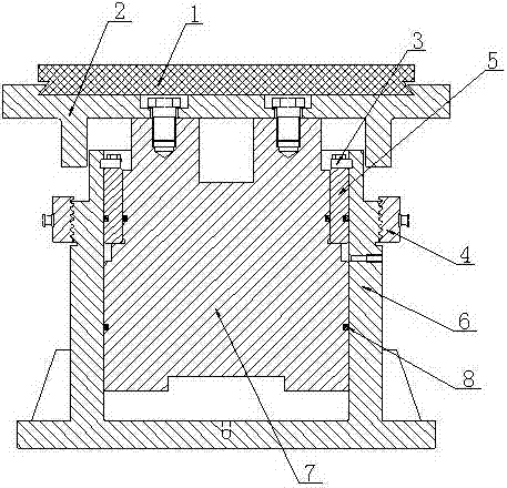
[0034] like Figure 4 ~ Figure 6 As shown, a single-piston three-chamber pneumatic return brake includes a piston cylinder 6 with a built-in piston 7. The upper end of the piston cylinder 6 is provided with a braking device fixedly connected to the piston 7. Between the piston 7 and the piston cylinder 6 A bushing 5 is provided, and the upper end of the bushing 5 is connected to the piston cylinder 6 through the bushing fixing plate 3, and is respectively arranged between the piston 7 and the piston cylinder 6, the piston 7 and the bushing 5, and the bushing 5 and the piston cylinder 6. There is a circular sealing ring 8 and a "Y" type sealing ring 9, and a locking device 4 is provided on the outer wall of the piston cylinder 6, and an isolation chamber 10 communicating with the outside atmosphere is also provided between the piston 7 and the piston cylinder 6, The side wall of the piston cylinder 6 facing the isolation chamber 10 is provided with a through hole 11 , and the c...


PUM


Abstract

The invention discloses a single-piston three-cavity pneumatic reset type brake and belongs to the technical field of braking of a hydro electric generating set. The problems that the performance of seal rings of the brake in the prior art is instable and gas leakage is easy to occur between upper and lower cavities are mainly solved. The brake comprises a piston cylinder in which a piston is arranged, wherein a braking device which is connected with the piston fixedly is arranged at the upper end of the piston cylinder; a bushing is arranged between the piston and the piston cylinder; the upper end of the bushing is connected with the piston cylinder through a bushing fixing plate; the seal rings are arranged between any two of the bushing, the piston and the piston cylinder respectively; a locking device is also arranged on an external wall of the piston cylinder; and an isolation cavity which is communicated with external air is also arranged between the piston and the piston cylinder. The invention also provides an implementation method of the brake. By smart fit of the implementation method and a brake structure, not only sealing performance is greatly improved, but also the gas leakage between the upper and lower cavities of the brake is effectively avoided, and the excellent working performance of the brake is guaranteed.

Description

Technical field [0001] The invention involves a brake, which specifically, involves a single piston pneumatic brake and its implementation method for single pistons in hydropower units. Background technique [0002] The brake (commonly known as the wind gate) is the core component of the brake system of the hydraulic power unit. Its structure mainly includes a piston tank with a piston, and the brake board above the piston tank. In the piston stand up the brake board and reset state, the bottom of the piston bottom, the bottom of the PistonsA cavity will be formed with the piston tank, referred to as the lower cavity, and the cavity formed between the top of the piston and the brake board is referred to as the upper cavity.During the working process of the hydropower unit, the brakes mainly have two functions: ① During the unit shutdown, when the speed drops to a lower speed, the piston in the brakes quickly stands up, and the brakes are added to avoid the unit to avoid the unit ...

Claims


Application Information

Patent Timeline
Patent Type & Authority Patents(China)
IPC IPC(8): F16D65/18F16D63/00F03B15/00F16D121/04F16D125/02F16D125/08
CPCY02E10/226Y02E10/20
Inventor 邓林森李攀光唐勇任开福任泽民栗建峰陈玉林张海滨
Owner DADU RIVER HYDROPOWER DEV
Learn More