Pressure-sensitive optical cable and manufacture method thereof

A pressure-sensitive, optical cable technology, applied in the direction of force measurement, fiber mechanical structure, etc. by measuring the change of optical properties of materials when they are stressed, which can solve unfavorable costs and mass production, limit the use of optical fiber sensors, production, packaging, etc. , transportation, difficulty in use and other problems, to achieve the effect of convenient processing, flexible use and simple structure

Inactive Publication Date: 2011-08-24
XIAN JINHE OPTICAL TECH
View PDF1 Cites 7 Cited by
  • Summary
  • Abstract
  • Description
  • Claims
  • Application Information

AI Technical Summary

Problems solved by technology

[0004] Chinese invention patent CN87107210 discloses a "microbending optical fiber strain gauge", which uses two plates with opposite, mutually staggered corrugated surfaces, and a signal optical fiber sandwiched between the two plates to achieve stress Sensing, its disadvantage is the use of two rigid boards, which limits the use of the fiber optic sensor, when it needs to be used in a large range and long distance, its production, packaging, transportation, and use are more difficult, so it is not necessary Facilitate cost reduction and mass production

Method used


Image

  • Pressure-sensitive optical cable and manufacture method thereof
  • Pressure-sensitive optical cable and manufacture method thereof
  • Pressure-sensitive optical cable and manufacture method thereof

Examples


Embodiment 1

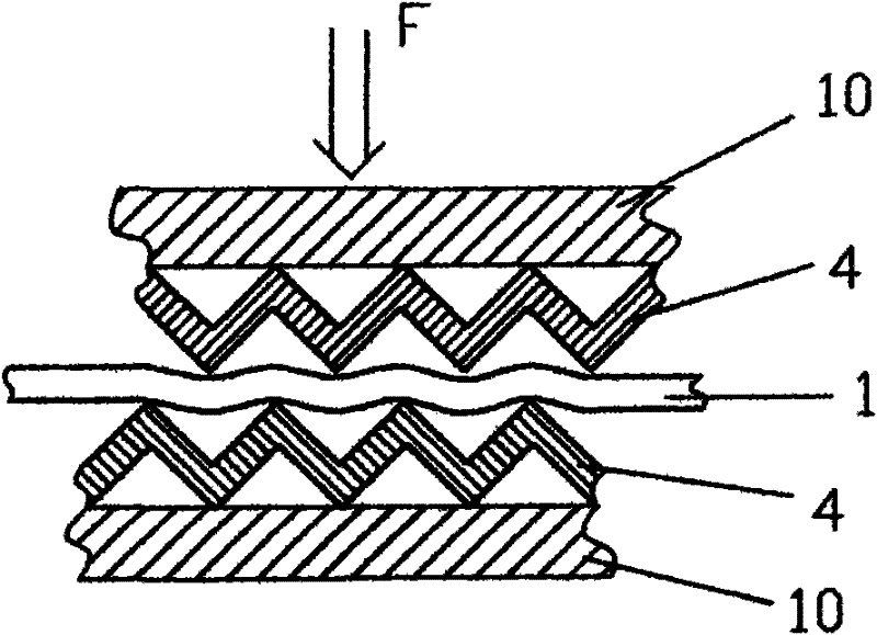
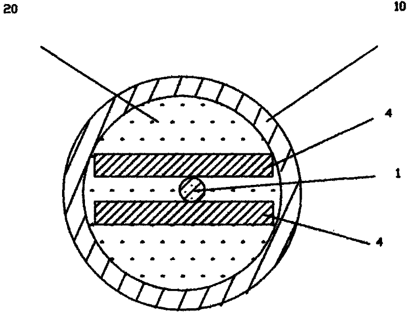
[0026] Such as figure 1 , figure 2 As shown, the present invention includes a toothed plate 4 made of flexible material, and a signal optical fiber 1 is sandwiched between the deformed teeth of the two toothed plates 4 , and the polymer sheath tube 10 wraps the two toothed plates 4 . During actual manufacturing, the void inside the polymer sheath tube is filled with water-blocking material 20 .

[0027] In this embodiment, the polymer sheath tube deforms under external pressure, thereby transmitting the external force to two tooth plates 4 made of flexible materials. Under the action of pressure, the two tooth plates 4 approach each other, and the The deformed teeth on the plate 4 will cause the signal optical fiber 1 to bend and deform, thereby changing the bending loss of the signal optical fiber 1 , thereby realizing the modulation of the light intensity in the signal optical fiber 1 . In this way, the pressure signal is converted into an optical signal and transmitted t...

Embodiment 2

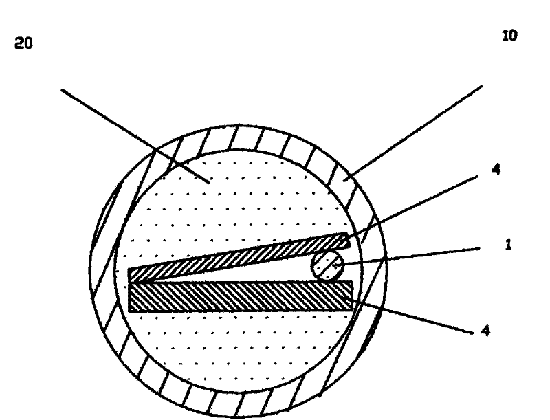
[0030] Such as image 3 As shown, in this embodiment, the difference from Embodiment 1 is that one side of the two tooth plates 4 is fixed together, which can prevent the pressure-sensitive optical cable from appearing in the processing and use of the two tooth plates 4 The relative movement causes the deformed teeth on the two tooth plates 4 to be unable to correspond alternately; in actual processing and production, the preferred manufacturing method is to make full use of the existing embossing machine of the optical cable manufacturer to make the tooth plates 4. The process is: There is a longitudinal dividing line, and on both sides of the dividing line, the staggered corresponding embossing is rolled out at the same time, and the embossing is the deformed tooth, and then the metal strip is folded in half along the dividing line, and two pieces with one side fixed together can be obtained. The tooth plate 4 can adjust the depth and the pitch of the embossing as required, ...


PUM


Abstract

The invention discloses a pressure-sensitive optical cable and a manufacture method thereof. The pressure-sensitive optical cable consists of two toothed plates made of a flexible material, and a polymer sheath tube sheathing the toothed plates, wherein the deformed teeth on the two toothed plates correspond to each other in a staggered manner; and a signal fiber is sandwiched by the deformed teeth of the two toothed plates. When a pressure is applied on the pressure-sensitive optical cable, the deformed teeth of the two toothed plates make relative movement so that the signal fiber generates bending deformation, thereby changing the bending loss of the signal fiber. Therefore, the pressure signal is converted into an optical signal, and is transmitted by the signal fiber to achieve the distal measurement. The toothed plate made of a flexible material has certain bending property, which can facilitate the manufacture, storage, transportation and use of the pressure-sensitive optical cable. Similar to the common optical cable, the pressure-sensitive optical cable has greatly reduced manufacture and use cost, and does not influence the pressure detection. The pressure-sensitive optical cable has the advantages of simple structure, reasonable design, convenience in manufacture, flexible use manner, high sensitivity and good use effect, and can achieve the distributed pressure measurement by use of measurement instruments, such as optical time-domain reflectometer.

Description

technical field [0001] The invention relates to an optical cable for pressure sensing, in particular to an optical cable for pressure sensing using the micro-bend loss of an optical fiber. Background technique [0002] There are many methods for measuring pressure in traditional pressure sensors, such as strain gauge measurement, optical measurement, Hall effect measurement, grating ruler measurement and so on. However, many current measurement methods are not conducive to remote measurement and monitoring, especially due to the interference of strong external electrical signals, serious distortion of remote transmission, complex measurement mechanism, poor reliability, and unfavorable maintenance. In addition, for flammable and explosive environments, all methods of using electrical measurement are not suitable, because any spark may cause serious fire or explosion accidents, causing immeasurable losses. The optical fiber stress sensor has many advantages and has attracted...

Claims


Application Information

Patent Timeline
Patent Type & Authority Applications(China)
IPC IPC(8): G02B6/44G01L1/24
Inventor 杜兵杜蔚杜迎涛
Owner XIAN JINHE OPTICAL TECH
Why Eureka
Try Eureka