A method for measuring a 2D angle of arrival (AOA) of coherently distributed signals

A measurement method and two-dimensional wave technology, which are applied to directions such as direction finders using radio waves, radio wave direction/bias determination systems, etc., can solve problems such as high complexity and large computational processing volume, and achieve high efficiency and accuracy. , the effect of reducing the complexity of processing and reducing the amount of computational processing

Inactive Publication Date: 2011-08-31
UNIV OF ELECTRONICS SCI & TECH OF CHINA
View PDF2 Cites 33 Cited by
  • Summary
  • Abstract
  • Description
  • Claims
  • Application Information

AI Technical Summary

Problems solved by technology

[0007] The solution of the present invention is aimed at the defects of the background technology, such as huge amount of calculation processing and high complexity. The present invention first uses the data received by the array itself to determine the propagation operator, and then uses the obtained propagation operator to determine the three translational sub-arrays. Rotation matrix, finally, use the eigenvalues ​​of the three rotation matrices to automatically pair the two-dimensional angle parameters of multiple distribution signals through the given parameter pairing method, and comprehensively determine the center azimuth and center elevation angle of each distribution signal to achieve The determination of multiple distributed signal orientations; to greatly reduce the amount of calculation and processing complexity, effectively improve the efficiency and accuracy of the measurement, so as to achieve the purpose of the invention

Method used


Image

  • A method for measuring a 2D angle of arrival (AOA) of coherently distributed signals
  • A method for measuring a 2D angle of arrival (AOA) of coherently distributed signals
  • A method for measuring a 2D angle of arrival (AOA) of coherently distributed signals

Examples


Embodiment Construction

[0026] The implementation method of the present invention will be described in further detail below in conjunction with the accompanying drawings:

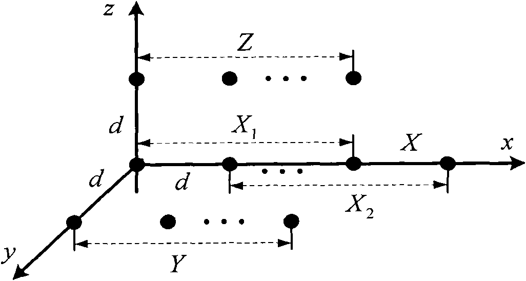
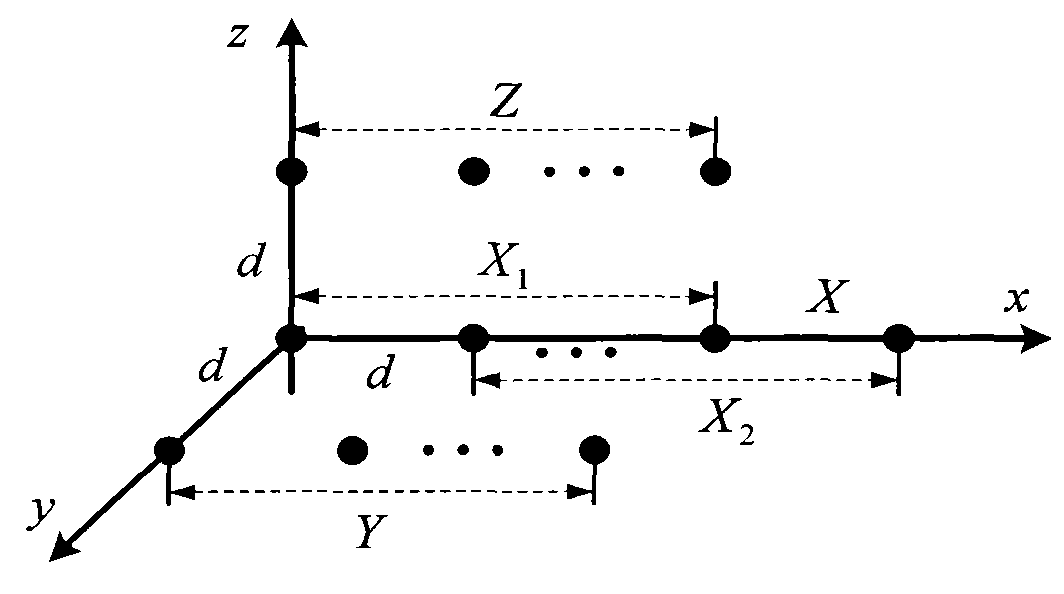
[0027] Step 1. Set up a three-dimensional antenna array: first set up a three-parallel uniform linear array X, Y and Z such as figure 1 The three-dimensional antenna array shown, wherein, the X array has M+1=11 array elements, the Y and Z arrays each have M=10 array elements, and the spacing of each array element on each parallel array is half a wavelength, and the Y The distance between Z and X is also half wavelength; the number of coherent distribution signals in this embodiment is D=3 narrowband coherent distribution signals, which are incident to this array from different directions, and the noise on each array element is additive Gaussian white Noise, and the noise is not related to the signal; for the two-dimensional coherent distribution signal array at time t, the received data vector is:

[0028] ...


PUM


Abstract

The invention provides a method for measuring a 2D angle of arrival (AOA) of coherently distributed signals. The method belongs to the technical field of wireless mobile communication technology. The method includes the steps of setting a stereoscopic antenna array composed of three parallel uniform linear arrays; establishing a data vector matrix and a propagator matrix of all the coherently distributed signals; eliminating aperture loss; establishing rotation matrixes and making pairing and combination of characteristic values of the rotation matrixes; and determining a central azimuth angle and a central pitch angle of the distributed signals. In the invention, the propagator is determined with received data firstly, then the three rotation matrixes are determined with the propagator, and finally the central azimuth angle and the central pitch angle of the distributed signals are comprehensively determined through automatically pairing the characteristic values of the three rotation matrixes by using the method in the invention, thereby improving the measuring precision to about 10 times higher than the precision of the prior art. Therefore, the method in the invention has characteristics of simplicity, high reliability, high performance in lowering the calculation processing capacity and complexity degree substantially, high measuring efficiency, high measuring precision degree and so on.

Description

technical field [0001] The invention belongs to the technical field of wireless mobile communication, and in particular relates to a method for measuring the two-dimensional direction of arrival (Direction of Arrival, referred to as DOA) of a coherent multipath distributed signal (referred to as a coherent distributed source) using an array antenna. test methods. Background technique [0002] The channel transmission environment of wireless mobile communication is complex and uncertain, and there are multipath fading and delay spread, resulting in inter-symbol interference (ISI), co-channel interference (CCI), multiple access interference (MAI), etc. These interferences Reduced link performance and system capacity. These types of interference can be countered or reduced by adopting technologies such as equalization, code matching filtering, RAKE reception, and channel coding and decoding. When these technologies utilize the time domain or frequency domain information of th...

Claims


Application Information

Patent Timeline
Patent Type & Authority Applications(China)
IPC IPC(8): G01S3/14
Inventor 郑植滕云龙
Owner UNIV OF ELECTRONICS SCI & TECH OF CHINA
Why Eureka
Try Eureka