Optical element axial adjusting device with aligning function

An optical element, axial adjustment technology, applied in optical elements, photolithographic process exposure devices, optics, etc., can solve problems such as radial errors, and achieve the effect of overcoming radial motion errors and improving performance

Inactive Publication Date: 2011-08-31
CHANGCHUN INST OF OPTICS FINE MECHANICS & PHYSICS CHINESE ACAD OF SCI
View PDF5 Cites 12 Cited by
  • Summary
  • Abstract
  • Description
  • Claims
  • Application Information

AI Technical Summary

Problems solved by technology

[0004] In order to solve the problem of radial error caused by the axial adjustment of the existing optical element axia

Method used


Image

  • Optical element axial adjusting device with aligning function
  • Optical element axial adjusting device with aligning function
  • Optical element axial adjusting device with aligning function

Examples


specific Embodiment approach 1

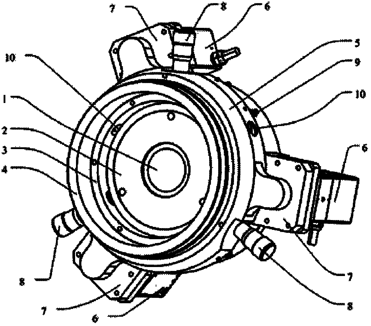
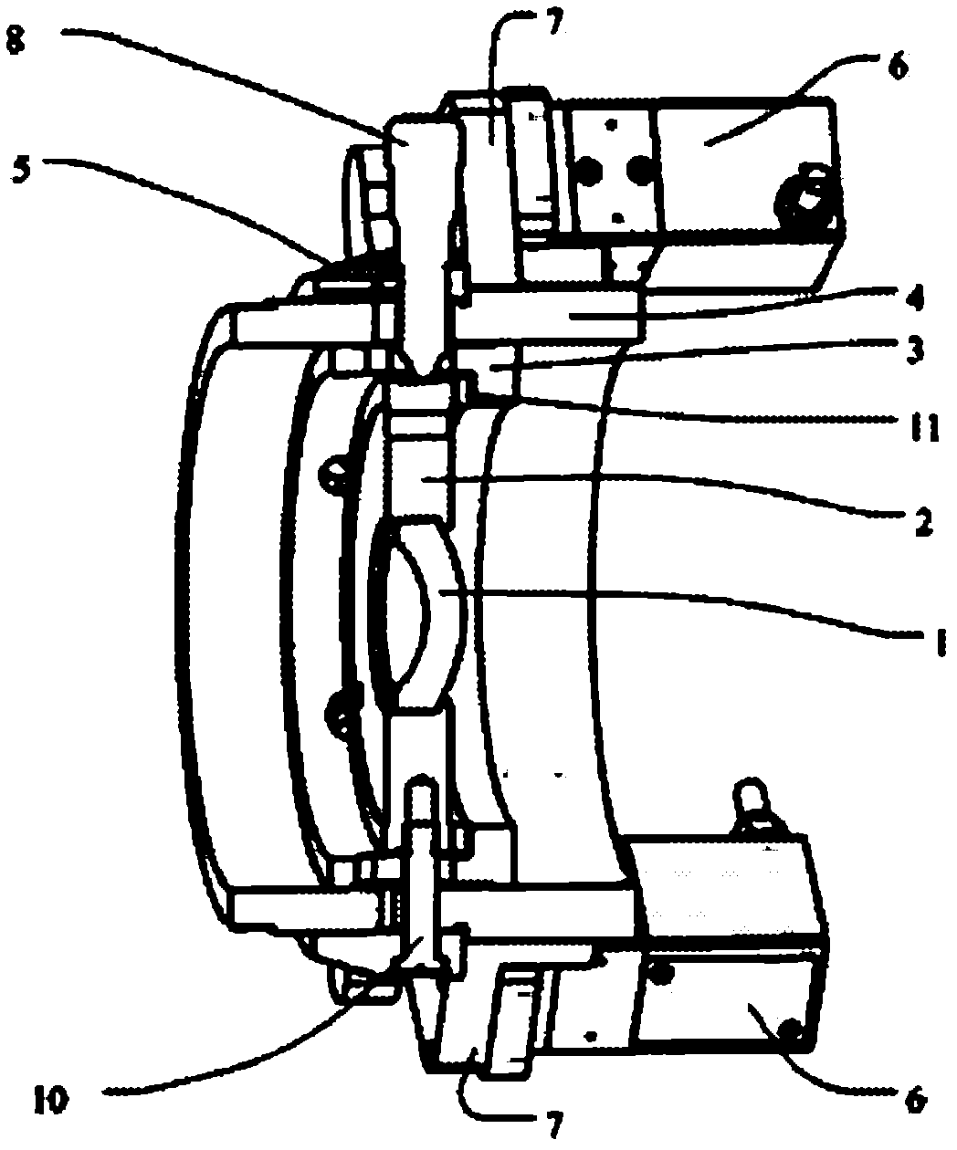
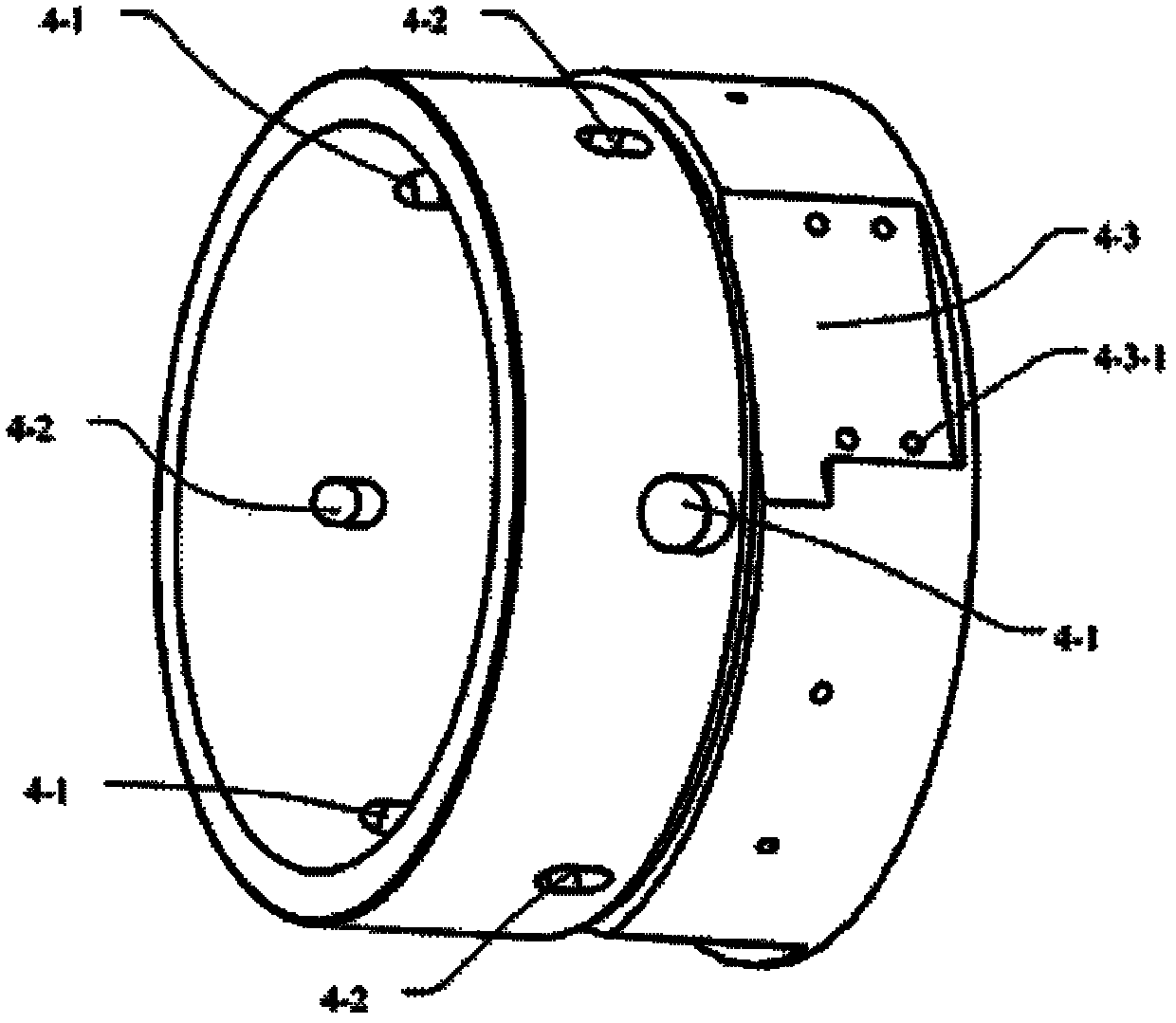
[0015] Specific implementation mode 1. Combination Figure 1 to Figure 6 Describe this embodiment, an optical element axial adjustment device with centering function, including an optical element 1, a mirror frame 2, a mirror holder 3, a lens barrel 4, a carriage 5, three piezoelectric drivers 6, three piezoelectric Driver base 7, three screw micrometers 8, three guide nails 10 and spring 9, the mirror base 3 is arranged in the lens barrel 4, the mirror frame 2 is arranged in the mirror mount 3, and the optical element 1 is arranged in the mirror frame 2 Inside; the slide frame 5 is installed on the upper stepped cylindrical surface of the lens barrel 4, and the three spiral micrometers 8 pass through the three spiral micrometer slide frame holes 5- 2. The three spiral micrometer lens barrel waist holes 4-1 set on the stepped cylindrical surface of the lens barrel 4 and the three spiral micrometer lens holder waist holes 3-2 set on the cylindrical surface of the mirror base 3 ...


PUM


Abstract

The invention provides an optical element axial adjusting device with an aligning function and relates to the technical field of deep ultraviolet lithography objective lens design and debugging. By using the device, the problem that the radial error is caused in the axial adjustment of the traditional optical element axial adjusting device is solved. The axial adjusting device can be regarded as a lens cone unit of an objective lens integrally, wherein a lens base is placed into the lens cone through the precise matching of an axle hole; a sliding frame is arranged on an external cylindrical surface of the lens cone; the lens base is used for aligning a lens frame component; the sliding frame is connected with an internal lens frame component through guide nails; the sliding frame is pushed by three piezoelectric drivers at the same time, so as to drive the lens frame and an optical element to axially move forwards; a recovering force supporting the sliding frame to retreat is supplied by a spring; and when any position of stroke is adjusted axially, the optical element can be aligned by precisely adjusting a spiral dial gauge and the guide nails. The axial adjusting device provided by the invention has the advantages of large adjustment stroke, high adjustment precision and the like and is convenient to operate.

Description

technical field [0001] The invention relates to the technical field of structural design and assembly of deep ultraviolet projection lithography objective lenses, and in particular to a device that can be used for axial adjustment of optical elements in a lithography projection objective lens system. Background technique [0002] Projection lithography equipment is the key equipment in the manufacturing process of large-scale integrated circuits. In recent years, with the continuous improvement of the line width of integrated circuits, the resolution of projection optical equipment has gradually improved. At present, the ArF excimer laser projection with a wavelength of 193.368nm Lithography equipment has become the mainstream equipment for integrated circuit manufacturing at 90nm, 65nm and 45nm nodes. In the structural design and assembly process of the projection lithography objective lens, various aberrations of the optical system need to be compensated in order to obtain...

Claims


Application Information

Patent Timeline
IPC IPC(8): G02B7/00G03F7/20
Inventor 赵磊巩岩张巍倪明阳
Owner CHANGCHUN INST OF OPTICS FINE MECHANICS & PHYSICS CHINESE ACAD OF SCI
Why Eureka
Try Eureka