A radio frequency front-end circuit structure

A technology of radio frequency front-end and circuit structure, applied in the direction of electrical components, transmission systems, etc., can solve the problems of affecting signal reception, increasing chip cost overhead, and inability to achieve impedance matching, etc., and achieve the effect of simple circuit structure, reducing cost and area

Inactive Publication Date: 2011-08-31
PEKING UNIV
View PDF6 Cites 29 Cited by
  • Summary
  • Abstract
  • Description
  • Claims
  • Application Information

AI Technical Summary

Problems solved by technology

Therefore, the duplexer must be used for isolation control between the antenna, receiver, and transmitter, otherwise, when used as a receiver, the impedance matching network of the transmitter PA will affect the input impedance Zin of the LNA in the receiver, making If it is not 50Ω, the LNA cannot achieve impedance matching, which seriously affects the signal reception; on the contrary, when it is used as a transmitter, ...

Method used


Image

  • A radio frequency front-end circuit structure
  • A radio frequency front-end circuit structure
  • A radio frequency front-end circuit structure

Examples


Embodiment Construction

[0033] The present invention will be described in detail below in conjunction with the accompanying drawings and specific embodiments.

[0034] In order to reduce the cost of the chip, a new RF front-end structure that can not only save the duplexer, but also enable the LNA and the PA to share an off-chip inductor is needed.

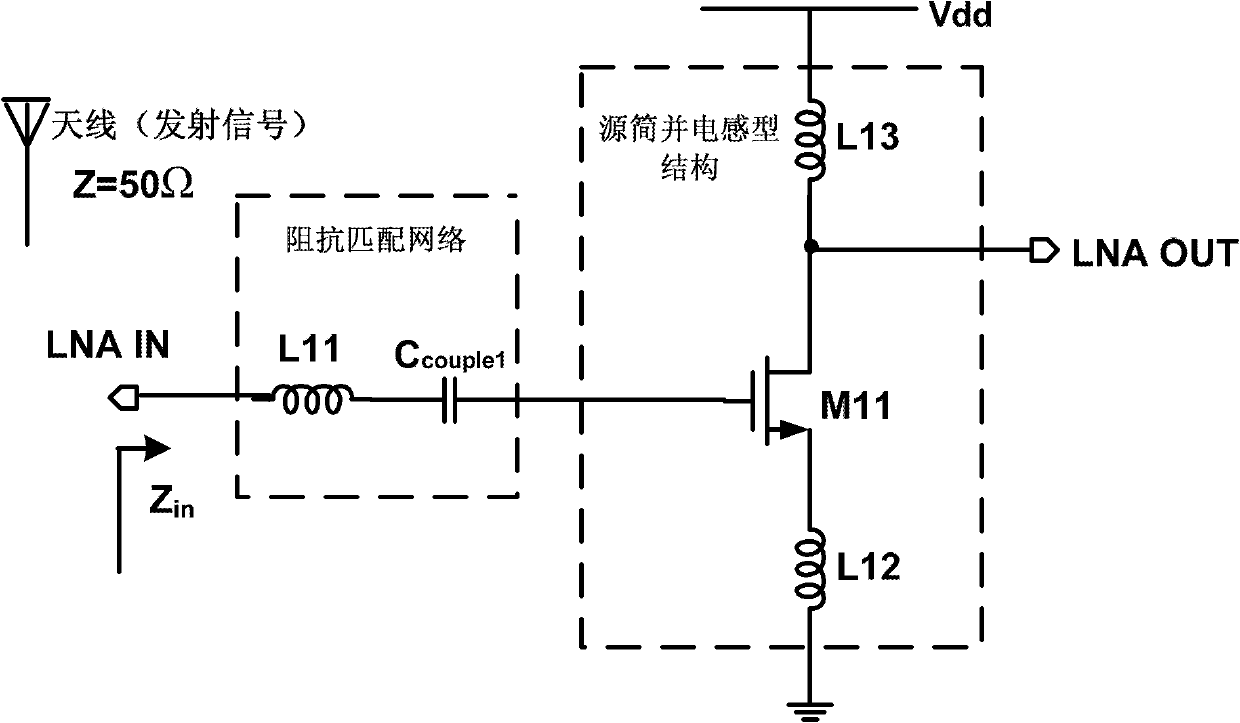
[0035] First of all, in the absence of a duplexer, in order to isolate the transmitting and receiving signals, the present invention must ensure that the transmitter and the receiver can work independently without affecting each other. Therefore, switching tubes are added to the LNA and the PA. These switching tubes The opening of the transceiver system is controlled by the enable signal generated by the digital baseband. Figure 5 It is a schematic diagram of the LNA structure after adding the switch tube. What the present invention adopts is the most common source degenerate structure (also can be a low noise amplifier with other structures), and M12 a...


PUM


Abstract

The invention provides a radio frequency front-end circuit structure, which comprises a receiver radio frequency front-end and a transmitter radio frequency front-end. A first switching tube is joined between a low noise amplifier in the receiver radio frequency front-end structure and an impedance matching network, a second switching tube is joined between the low noise amplifier and a power supply, a third switching tube is joined between a radio frequency power amplifier in the transmitter radio frequency front-end structure and the impedance matching network, and a fourth switching tube is joined between the radio frequency power amplifier and the power supply. Enablement of all the above-mentioned switching tubes is controlled by enable signals generated by a digital baseband, and the low noise amplifier and the radio frequency power amplifier employ the same off-chip inductor, which is connected with a receiving antenna. The radio frequency front-end circuit structure in the invention is simple without a duplexer and guarantees the proper functioning of a transceiver in two states; has only one off-chip inductor instead of two, thereby reducing the cost and area of passive devices; and guarantees all the performances of the transceiver.

Description

technical field [0001] The invention belongs to the field of radio frequency integrated circuits, and in particular relates to a radio frequency front-end circuit structure. Background technique [0002] In the past ten years, the development and research of radio frequency integrated circuits (RFICs) have developed rapidly, which is mainly due to the prosperity of the wireless communication market. These wireless applications include pagers, cordless phones, radio frequency identification (RFID), digital cellular mobile phones (GSM, CDMA) and the global positioning system (GPS). [0003] The market has higher and higher performance requirements for wireless products. In emerging electronic consumer products, it is especially necessary to meet the requirements of low cost, low power consumption, small size, and high performance. Improving the integration of transceivers is undoubtedly to meet the above requirements. important way. [0004] The wireless transceiver (transmi...

Claims


Application Information

Patent Timeline
IPC IPC(8): H04B1/40
Inventor 刘军华聂楠李琛廖怀林
Owner PEKING UNIV
Why Eureka
Try Eureka