Method for operating an internal combustion engine

一种内燃机、燃料消耗的技术,应用在内燃活塞发动机、燃烧发动机、机械设备等方向,能够解决小喷射时间、气态排出体积流量不可控制等问题

Active Publication Date: 2011-08-31
ROBERT BOSCH GMBH
View PDF7 Cites 7 Cited by
  • Summary
  • Abstract
  • Description
  • Claims
  • Application Information

AI Technical Summary

Problems solved by technology

[0007] If the internal combustion engine is warmed up for a short period of time (e.g. due to high load and high rotational speed) with such high levels of fuel added to the engine oil and is then run idling, the gaseous exhaust volume flow is often uncontrollable
Further leaning by the injection valve is then often not possible because the minimum injection time has already been reached

Method used


Image

  • Method for operating an internal combustion engine
  • Method for operating an internal combustion engine
  • Method for operating an internal combustion engine

Examples


Embodiment Construction

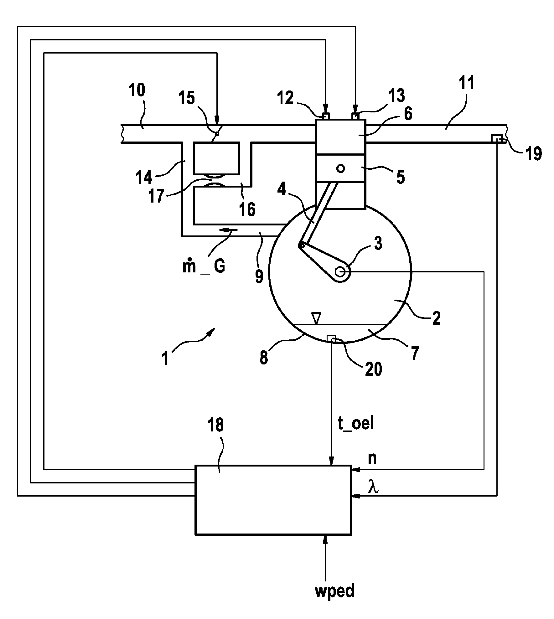
[0021] figure 1 A schematic diagram of an internal combustion engine 1 with a crankcase 2 in which a crankshaft 3 is arranged is shown. The crankshaft 3 is connected with the piston 5 through the connecting rod 4, and the piston 5 is arranged on the cylinder 6 in a manner capable of moving back and forth. For the sake of simplicity, only one cylinder of an internal combustion engine is shown here, usually an internal combustion engine has multiple cylinders, eg 4 or 6 cylinders. Engine oil 7 is located in the crankcase 2 , which is delivered to the corresponding lubrication points, in particular also to the running surfaces of the piston 5 in the cylinder 6 , via lines and pumps not shown here. Engine oil accumulates in the oil pan 8 . In order to reduce the excess pressure in the piston box 2 , the piston box 2 is connected by an exhaust line 9 to an intake system 10 of the internal combustion engine. Ambient air is sucked into the cylinder 6 via an intake system 10 in a m...


PUM


Abstract

The invention relates to a method for operating an internal combustion engine, wherein a crank housing (2) of the internal combustion engine comprises a ventilation (9) into the intake tract (10) of the internal combustion engine, characterized in that, during the outgassing of fuel from engine oil present in the crank housing (2), the operating point of the internal combustion engine is modified such that a predeterminable air / fuel ratio is not fallen below.

Description

technical field [0001] The invention relates to a method for operating an internal combustion engine, wherein the crankcase of the internal combustion engine has an exhaust gas line leading into an intake system of the internal combustion engine. Background technique [0002] The crankcase of the internal combustion engine does not close tightly. Small airflows flow past the piston rings, which would generate high pressure in the crankcase without openings in the crankcase. This pressure build-up is avoided by the so-called crankcase vent line. The crankcase exhaust gas line conducts gases from the crankcase into the intake manifold and from there into the intake system of the internal combustion engine. Avoid direct connection to the suction manifold vacuum here, since otherwise the crankcase would be placed at the suction manifold pressure level. [0003] Via the piston rings, not only the combusted so-called blow-by gas (Blow-By-Gase) is pressed into the crankcase, but...

Claims


Application Information

Patent Timeline
Patent Type & Authority Applications(China)
IPC IPC(8): F02D41/04F02D19/00F02D37/02F02D41/40F02D41/08F02D41/12F01M13/00
CPCF02D41/40Y02T10/44F02D37/02F02D2250/22F02D41/047F02D41/12F02D41/0002F02D41/08F02D41/003Y02T10/40
Inventor G.马勒布赖因C.夫拉德J.赖特
Owner ROBERT BOSCH GMBH
Why Eureka
Try Eureka