Al technical title is built by PatSnap Al team. It summarizes the technical point description of the patent document.
A forming machine and shearing technology, which is applied in the direction of material forming presses, presses, manufacturing tools, etc., can solve the problems of easy carbonization and crash of equipment, and achieve the effects of not easy to crash, less friction, and ingenious technology
Inactive Publication Date: 2011-09-07
潘留华 +1
View PDF4 Cites 2 Cited by
Summary
Abstract
Description
Claims
Application Information
AI Technical Summary
This helps you quickly interpret patents by identifying the three key elements:
Problems solved by technology
Method used
Benefits of technology
Problems solved by technology
[0003] There are also various series of straw coal forming machines on the market, but all kinds of equipment have problems such as easy carbonization and crash; and when the grass cavity is rolling and briquetting, there are straws of different lengths that cannot be handled by themselves and are pressed on the rollers. Lower the roller so that it doesn’t move; when the roller gathers too much straw, the straw will be rolled into a slurry, so that it will be carbonized and agglomerated to cause the machine to crash
Method used
Image
Click on the blue label to locate the original text in one second.
Reading with bidirectional positioning of images and text.
Examples
Embodiment Construction
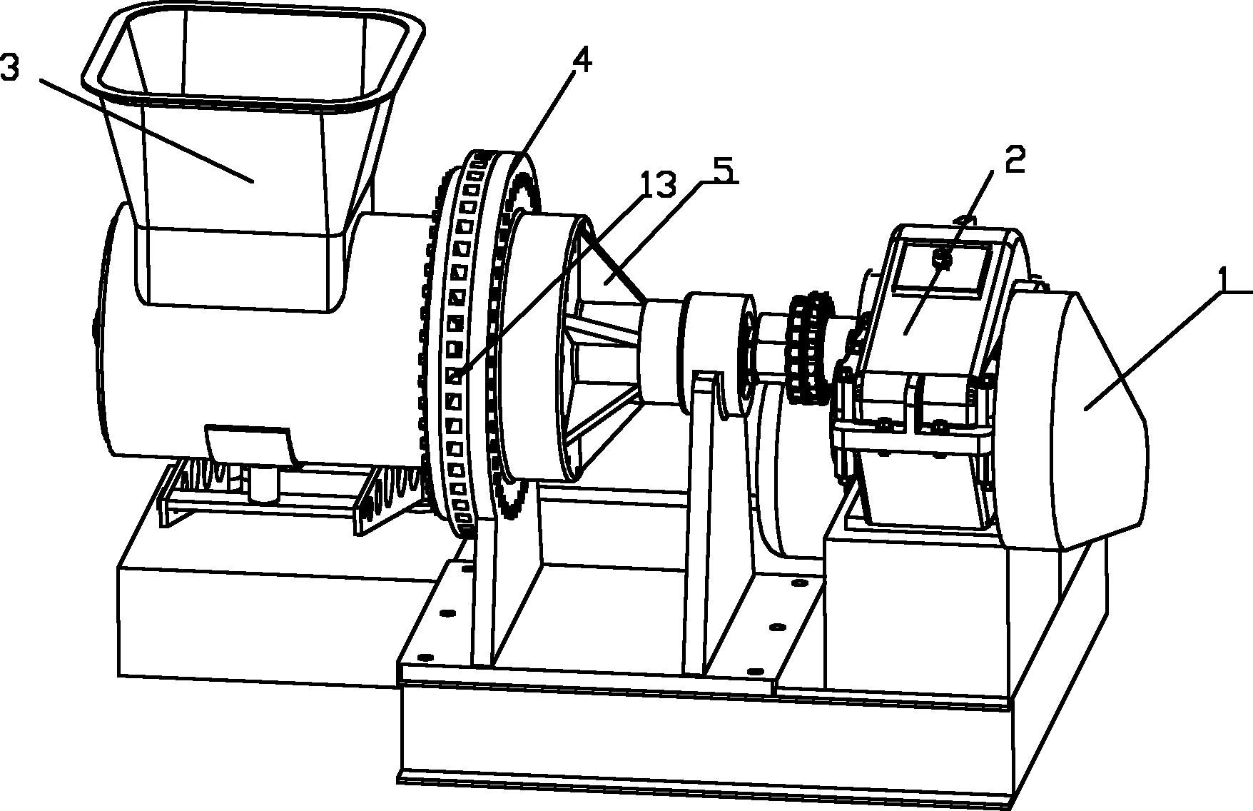
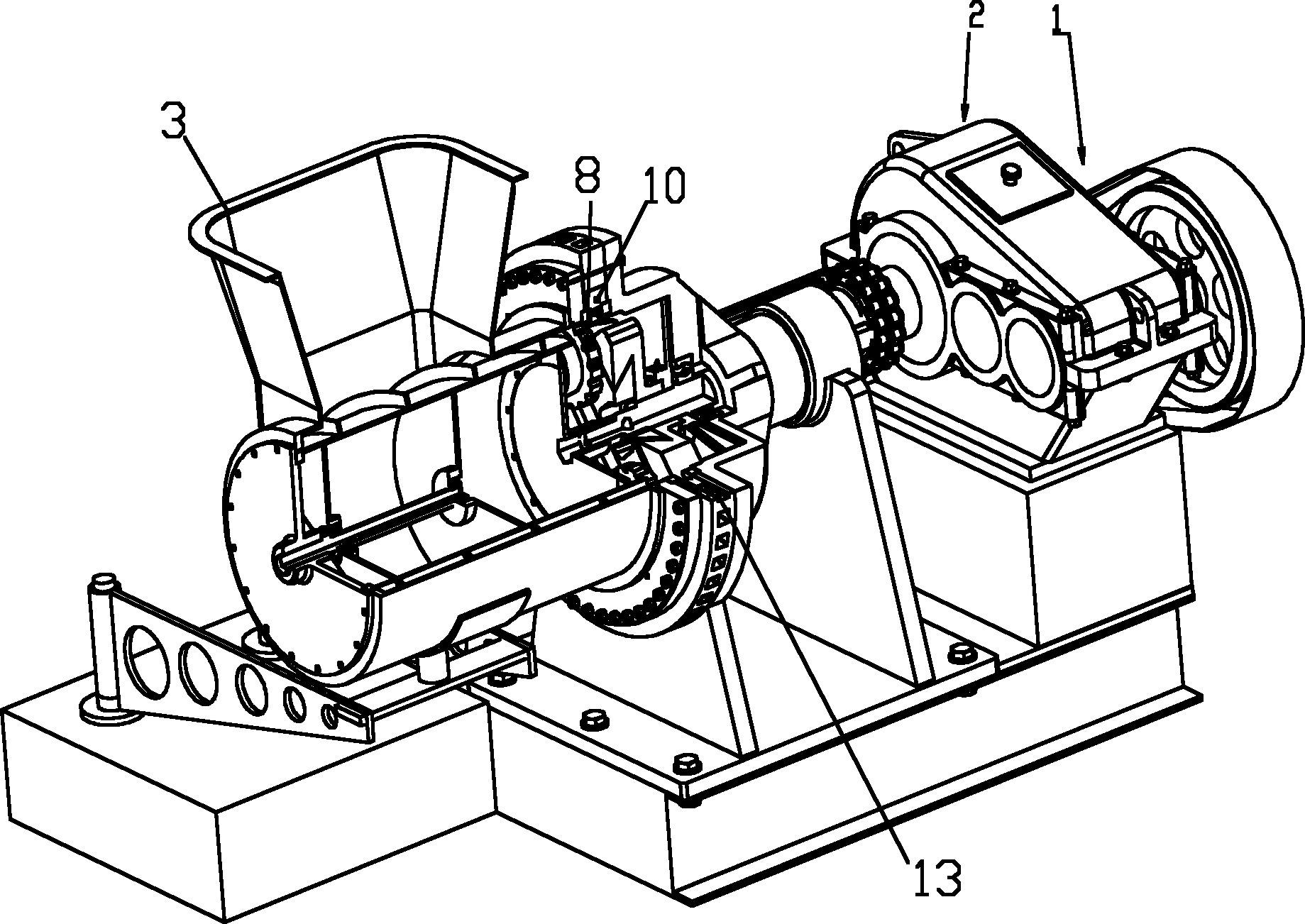
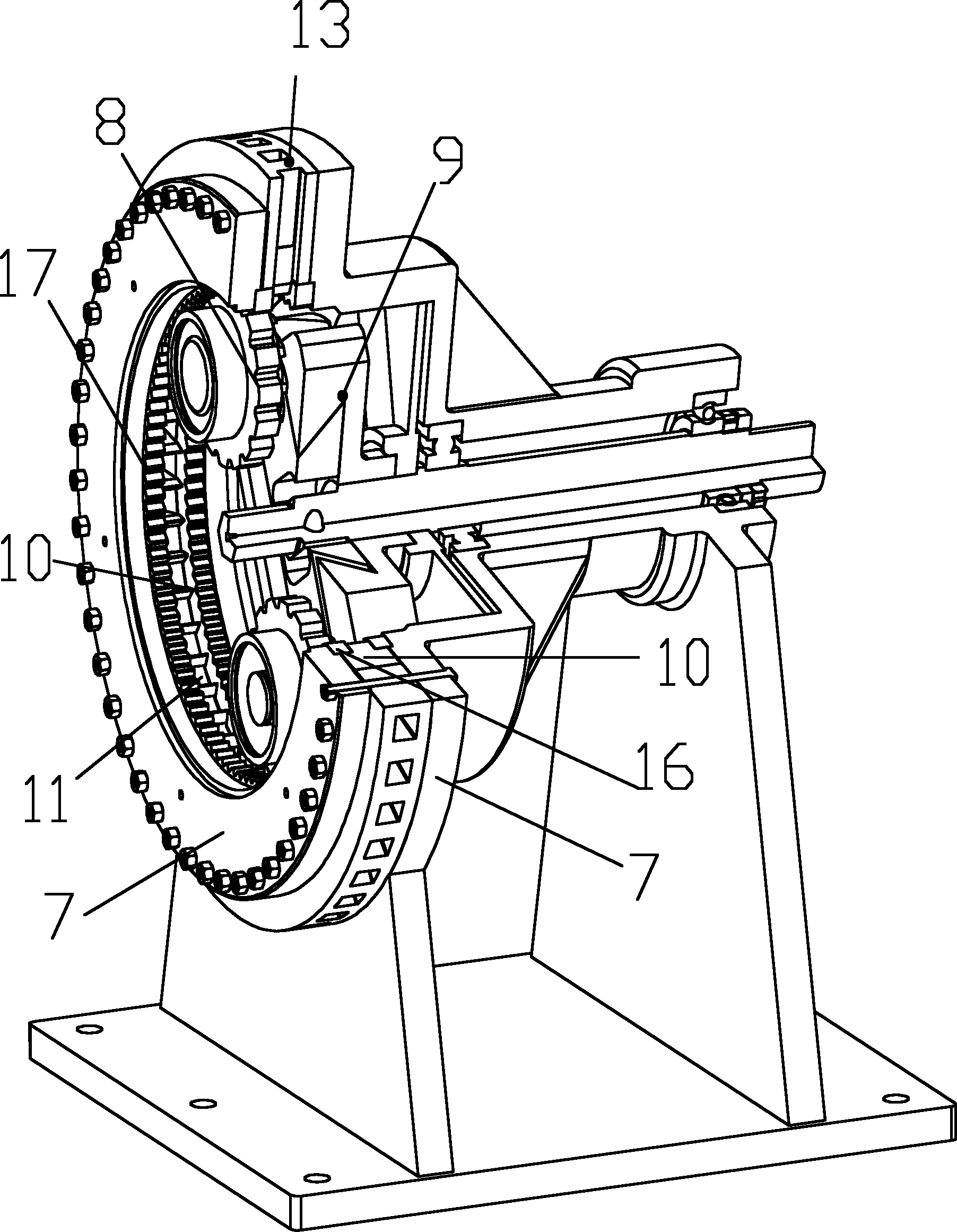
[0022] Below in conjunction with accompanying drawing, the present invention is described in further detail. As shown in the figure, the figure includes: power device 1, transmission device 2, feeding device 3, straw briquette forming device 4, frame 5, knife body 6, round blade 7, toothed hob 8, adjustable hob Knife holder 9, wire cutting trapezoidal sharp knife 10, trumpet-shaped feed port 11, annular knife groove 12, discharge cavity 13, knife holder 14 of the knife body, cutter teeth 15 of the circular blade, rake face and center surface of the cutter teeth The included angle A, the included angle B between the cutter flank and the center plane.
[0023] figure 1 It is an overall schematic diagram of the rolling shear type straw briquetting machine of the present invention. It can be seen that the power unit 1 is connected with the straw briquette forming device 4 through the transmission device 2 , and the straw briquette forming device 4 is connected with the feeding d...
PUM
Abstract
The invention discloses a rolling shear type straw briquetting machine which comprises a power device, a transmission device, a feeding device and a straw briquetting device, wherein the power device is connected with the transmission device, the transmission device is connected with a frame, the frame is provided with the straw briquetting device, and the feeding device is connected with the straw briquetting device. The rolling shear type straw briquetting machine is characterized in that the straw briquetting device comprises a cutter main body, round blades, hobbing cutters and a hobbing cutter rest, wherein the inside of the cutter main body is provided with cutter teeth, a tapered feed inlet is formed between two adjacent cutter teeth, the two sides of the cutter main body are respectively provided with a round blade, the inside of each round blade is provided with cutter teeth, the hobbing cutter rest is connected with the frame, at least two hobbing cutters are arranged on the hobbing cutter rest, the blade of each hobbing cutter is arranged in an annular cutter groove formed between the round blades and the cutter main body, and the hobbing cutters are driven by the hobbing cutter rest so as to rotate along the annular cutter groove. By using the rolling shear type straw briquetting machine disclosed by the invention, the production efficiency is greatly improved, the machine is not easy to crash, and the straws are not easy to carbonize, therefore, the machine complies with the orientation of national environmental protection policies.
Description
technical field [0001] The invention relates to a straw briquette forming machine, in particular to a device for rolling, shearing and extrusion forming by using a blade. Background technique [0002] "Straw briquette forming machine" refers to the use of rural corn stalks, wheat straws, cotton stalks, straw, rice husks, peanut shells, corncobs, branches, leaves, sawdust and other crops and solid waste as raw materials, which are crushed and processed Compressed and densified, it is called "straw coal". The formed straw charcoal block is small in size, heavy in proportion, resistant to combustion, and convenient for storage and transportation. cm3, the calorific value can reach between 3500-5500 kcal, it is a solid fuel with high volatile content. "Straw briquetting machine" can replace firewood, raw coal, liquefied petroleum gas, etc., and is widely used in domestic stoves, heating furnaces, hot water boilers, industrial boilers, biomass power plants, etc. The combustion...
Claims
Application Information
Patent Timeline
Application Date:The date an application was filed.
Publication Date:The date a patent or application was officially published.
First Publication Date:The earliest publication date of a patent with the same application number.
Issue Date:Publication date of the patent grant document.
PCT Entry Date:The Entry date of PCT National Phase.
Estimated Expiry Date:The statutory expiry date of a patent right according to the Patent Law, and it is the longest term of protection that the patent right can achieve without the termination of the patent right due to other reasons(Term extension factor has been taken into account ).
Invalid Date:Actual expiry date is based on effective date or publication date of legal transaction data of invalid patent.