
Medium-pressure gas collection technique based on cluster well

A cluster well and gas gathering technology, which is applied in earthwork drilling, wellbore/well components, and production fluids, etc., can solve the problems of increasing engineering investment and operating costs, unfavorable formation pressure utilization, and high design pressure of alcohol injection pipelines. , to achieve the effect of improving liquid carrying capacity, convenient management, and small maintenance workload

Active Publication Date: 2013-11-27
XIAN CHANGQING TECH ENG
View PDF1 Cites 0 Cited by
  • Summary
  • Abstract
  • Description
  • Claims
  • Application Information

AI Technical Summary

Problems solved by technology

Cluster wells are to build several gas wells in one well site, generally 3 to 9 wells. The production of the well group is high, and the pressure decline is relatively slow. If the gas gathering station installs the compressor in advance, it is not conducive to the utilization of formation pressure; the diameter of the gas production pipeline increases, which increases the project investment and operation cost
If the high-pressure gas gathering method is used, the stable production time is relatively short compared with the high-yield gas field, and the design pressure of the pipeline is high, so it is abandoned prematurely; the alcohol injection pipeline is injected at the gas gathering station, resulting in high design pressure, long pipeline, high investment, and poor overall economy

Method used


Image

  • Medium-pressure gas collection technique based on cluster well
  • Medium-pressure gas collection technique based on cluster well

Examples


Embodiment 1

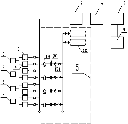
[0019] Such as figure 1 , figure 2 As shown in the structural diagram of the medium pressure gas gathering process, it includes cluster well group 1, wellhead device 2, gas production branch line 3, alcohol injection pipeline 4, alcohol injection device 5, gas production main pipe 6, gas gathering station 7. Gas gathering branch line 8. Central processing plant 9.

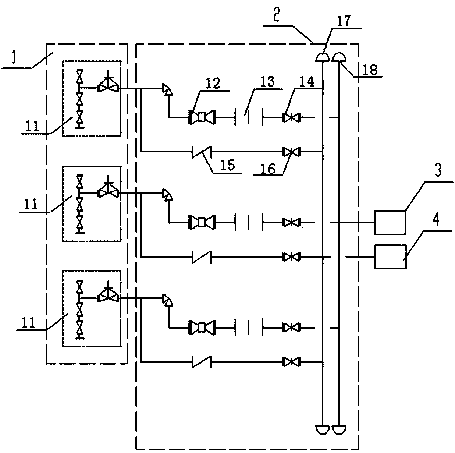
[0020] The cluster well group 1 is composed of 3 to 9 natural gas wells 11. There are downhole chokes in the gas wells 11. The distance between the downhole chokes and the wellhead device is 1500 meters to 3000 meters. Each gas well 11 passes through the downhole chokes. Reduce the wellhead pressure to medium pressure, and then through the wellhead device 2 and the gas production branch line 3, the natural gas generated by each gas well 11 of the cluster well group 1 is metered and transported to the next collected well group, and the surrounding cluster well group 1 gathers Afterwards, it is transported to the ...

Embodiment 2

[0024] The wellhead device 2 in the foregoing embodiment comprises a wellhead shut-off valve 12, a flow meter 13, a natural gas shut-off valve 14, a check valve 15, a methanol shut-off valve 16, a methanol manifold 17, and a natural gas manifold 18. The wellhead of the gas well 11 is divided into two One of them connects the wellhead shut-off valve 12, the flow meter 13, and the natural gas shut-off valve 14 in series to form a natural gas pipeline, and the natural gas manifold 18 gathers the natural gas pipelines of other gas wells 11 in the cluster well group 1 Afterwards, it is connected with the gas production branch line 3; the other one connects the check valve 15 and the methanol shut-off valve 16 in series and connects them with the methanol manifold 17 to form an alcohol injection pipeline. After the alcohol pipelines are collected, they are connected with the alcohol injection pipeline 4, and the check valve 15 ensures that natural gas will not enter the alcohol injec...

Embodiment 3

[0026] The alcohol injection device 5 in embodiment 1 is made up of methanol storage tank 10, alcohol injection pump 19, methanol flowmeter 20, filter 21, and the alcohol injection pipeline 4 connected to each gas well 11 all passes through alcohol injection pump 19, methanol flow rate respectively. A meter 20 and a filter 21 are connected to the outlet end of the methanol storage tank 10 in sequence.

[0027] The methanol in the methanol storage tank 10 is filtered and measured by the filter 21 and the methanol flowmeter 20, and after being pressurized by the alcohol injection pump 19, the methanol in the methanol storage tank 10 is injected into the gas well 11 through the alcohol injection pipeline 4, and the methanol and natural gas pass through the wellhead together. The natural gas pipeline of device 2 enters the gas extraction branch line 3 .


PUM


Abstract

The invention relates to a gas field transmission device based on a cluster well, in particular to a medium-pressure gas collection technique based on the cluster well, comprising gas wells, gas collecting branches, gas collecting main pipes, and a gas collection station in the cluster well set, wherein each gas well is provided with a well throttling machine. The medium-pressure gas collection technique is characterized in that: each gas well is used for reducing the well mouth pressure to the medium pressure through the well throttling machine, and uniformly transmits the natural gas generated by the gas wells of the cluster well set through a well mouth device and the gas collection branches to the next gathered well set after counting; the peripheral cluster well sets are gathered to be sent to the gas collection station through the gas collection main pipes; methanol injecting pipelines are arranged along the gas collection branches in the same slot to inject methanol to the cluster well sets through methanol injecting devices; and the methanol injecting devices are synchronously used to inject the methanol to the well set and the peripheral well sets. Under the condition of saving cost and simplifying technique, the natural gas in the well can be safely transported to a center processing factory to manage by fully using formation pressure without a heating furnace on the well mouth or the gas collection station, and a compressor at the gas collection station.

Description

technical field [0001] The invention relates to a gas field gas transmission device based on cluster wells, in particular to a medium-pressure gas gathering process based on cluster wells. Background technique [0002] Gas gathering methods commonly used in gas fields include high pressure gas gathering method and medium and low pressure gas gathering method. [0003] The high-pressure gas gathering method is mainly suitable for gas fields with high output and strong production stability. Since the natural gas output directly from the well has a high pressure, in order to safely transport the natural gas to the gas gathering station for gas-liquid separation, the natural gas is then transferred to the To transport to the central treatment plant for deoiling and dehydration, it is necessary to inject hydrate inhibitor methanol into the wellhead from the gas gathering station to prevent the pipeline from freezing and blocking. When the number of wells in the gas field is larg...

Claims


Application Information

Patent Timeline
Patent Type & Authority Patents(China)
IPC IPC(8): E21B43/00E21B43/12E21B43/22E21B33/03
Inventor 刘银春刘祎郑欣刘子兵常志波张凤喜杨家茂
Owner XIAN CHANGQING TECH ENG
Learn More