Method and device for centering initial welding positions of flat narrow welding lines and tracking welding lines

A welding position and flat plate technology, applied in position/direction control, welding equipment, arc welding equipment, etc., can solve problems such as no consideration, and achieve the effect of low cost of use, strong usability, simple and reliable method

Inactive Publication Date: 2011-09-14
INST OF AUTOMATION CHINESE ACAD OF SCI
View PDF10 Cites 13 Cited by
  • Summary
  • Abstract
  • Description
  • Claims
  • Application Information

AI Technical Summary

Problems solved by technology

In terms of initial welding position alignment, currently there is only a method to find the initial point in the image space, without considering how to achieve the initial welding position alignment whe

Method used


Image

  • Method and device for centering initial welding positions of flat narrow welding lines and tracking welding lines
  • Method and device for centering initial welding positions of flat narrow welding lines and tracking welding lines
  • Method and device for centering initial welding positions of flat narrow welding lines and tracking welding lines

Examples


Embodiment Construction

[0015] In order to make the object, technical solution and advantages of the present invention clearer, the present invention will be described in further detail below in conjunction with specific embodiments and with reference to the accompanying drawings.

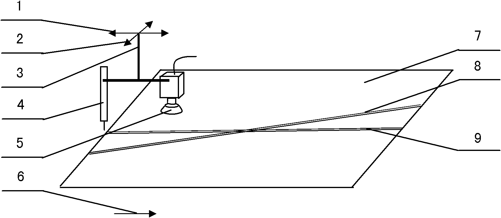
[0016] see figure 1 It is the schematic diagram of the initial welding position centering of the flat narrow weld seam, figure 1 It includes a traveling mechanism 1, an adjusting mechanism 2, a connecting rod 3, a welding torch 4, a camera 5 and a PID controller, wherein the traveling mechanism 1 and the adjusting mechanism 2 are symmetrically connected to the center, and one end of the vertical part of the connecting rod 3 is located in the traveling mechanism 1, perpendicular to each other and fixedly connected; the welding torch 4 and the camera 5 are respectively fixed at both ends of the horizontal part of the connecting rod 3, and the connecting rod 3 is fixedly connected to the welding torch 4 and the camera 5 as a...


PUM


Abstract

The invention discloses a method and a device for centering initial welding positions of flat narrow welding lines and tracking welding lines. In the method and the device, a traveling mechanism is connected with an adjusting mechanism in a central symmetry mode; one end of a vertical part of a connecting rod is positioned in the center of the traveling mechanism, and is vertical to the travelingmechanism and fixedly connected with the traveling mechanism; a welding gun and a camera are respectively fixed at two ends of a horizontal part of the connecting part of the connecting rod; the connecting rod fixedly connects the welding gun and the camera into a whole; the traveling mechanism is used for controlling the welding gun and the camera to move along the horizontal direction of a welding line of a weldment; the adjusting mechanism is used for controlling the welding gun and the camera to move in a direction vertical to the welding line of the weldment; position data of the traveling mechanism and characteristic point image data of the welding line are utilized to realize the automatic centering of the initial welding positions, and the current characteristic point image coordinate of the welding line is obtained and is taken as a reference image coordinate FC0i; and a proportional-integral-derivative (PID) controller controls and adjusts the movement of the traveling mechanism according to the deviation of the reference image coordinate FC0i of the welding line and the current image coordinate FCi of the welding line.

Description

technical field [0001] The invention belongs to welding automation in the field of industrial automation, and specifically uses vision to guide a welding torch to automatically align with the initial welding position of a welding seam, and guides the welding torch to automatically track the welding seam during the welding process. Background technique [0002] Vision-based intelligent welding robots mainly have three functions: initial welding position recognition and guidance based on vision sensing, weld seam tracking based on vision sensing, and real-time control of weld penetration based on vision sensing (see "Chen Shanben , Lin Tao, etc., Intelligent Welding Robot Technology, pp. 20-22, Beijing: Machinery Industry Press, 2006"). In practical applications, when the welding parameters and process characteristics are determined, the weld penetration is mainly affected by the initial welding position positioning accuracy and weld seam tracking accuracy. [0003] Therefore...

Claims


Application Information

Patent Timeline
IPC IPC(8): B23K9/127G05D3/00
Inventor 徐德谭民方灶军
Owner INST OF AUTOMATION CHINESE ACAD OF SCI
Why Eureka
Try Eureka