
Method and detection sensor for detecting optical fiber grating vibration of large-scale mechanized equipment

A fiber grating and large-scale machinery technology, applied in the field of sensors, can solve problems such as poor frequency dynamic response characteristics, obstacles to the application of rotating machinery, and inability to apply high-frequency measurement, etc., to achieve fast dynamic response, eliminate influence, and anti-electromagnetic interference. strong effect

Inactive Publication Date: 2012-07-04
WUHAN UNIV OF TECH +1
View PDF0 Cites 0 Cited by
  • Summary
  • Abstract
  • Description
  • Claims
  • Application Information

AI Technical Summary

Problems solved by technology

The cantilever beam fiber grating sensor has poor dynamic response characteristics to frequency and cannot be applied to high frequency measurement
In addition, because the transmission line of the contact fiber grating sensor is easily entangled with the rotating body or rotating shaft, it also hinders its application in the health monitoring of rotating machinery

Method used


Image

  • Method and detection sensor for detecting optical fiber grating vibration of large-scale mechanized equipment
  • Method and detection sensor for detecting optical fiber grating vibration of large-scale mechanized equipment
  • Method and detection sensor for detecting optical fiber grating vibration of large-scale mechanized equipment

Examples


Embodiment Construction

[0022] The present invention will be described in further detail below in conjunction with the accompanying drawings.

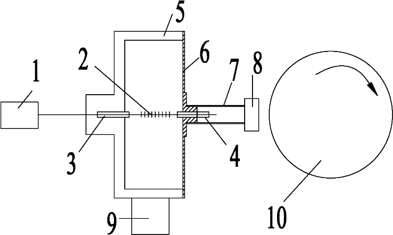
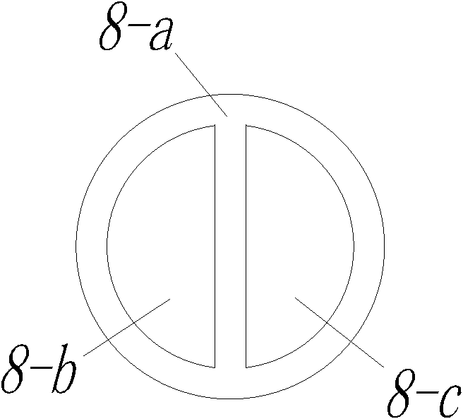
[0023] The overall installation structure of the non-contact fiber grating dynamic detection sensor: the two ends of the fiber grating 2 are respectively glued into the first capillary steel pipe 3 and the second capillary steel pipe 4, wherein the first capillary steel pipe 3 is connected to one end of the metal sleeve 5, The second capillary steel pipe 4 is connected to the central hard core of the metal diaphragm 6, and the metal diaphragm 6 is welded to the other end of the metal sleeve 5. During the installation process, the fiber grating 2 is pre-tightened, and the first magnet 8-b and The second magnet 8-c is a U-shaped sensing probe formed by connecting the soft iron 8-a—the magnetic coupling sensing probe 8, and the magnetic coupling sensing probe 8 is connected to the central hard core of the metal diaphragm 6 through the connecting rod 7 , which co...


PUM


Abstract

The invention discloses a method and a detection sensor for detecting optical fiber grating vibration of large-scale mechanized equipment. A sensor probe part mainly comprises two parts, namely a magnetic coupling sensing probe and an optical fiber grating sensing probe. When the vibration of the large-scale mechanized equipment is detected, the magnetic coupling sensing probe, a metallic membrane, an optical fiber grating in the sensor are connected with an optical fiber grating demodulating system in sequence, and the magnetic coupling sensing probe faces an object to be measured. A magnetic coupling force is generated between the magnetic coupling sensing probe and the object to be measured to promote a displacement change of the magnetic coupling probe, which results in offset of the centre of the metallic membrane from an original position and drift of an fiber grating wavelength in sequence; and the optical fiber grating demodulating system obtains a drift value of the fiber grating wavelength and analyzes the overall process. The detection sensor is simple in structure, convenient to manufacture and install, high in sensitivity, strong in anti-electromagnetic interference capability, high in frequency dynamic response speed, can transmit signal remotely, can detect the high-frequency signal and is not affected by temperature, so the invention can be used in severe environment and inflammable and explosive locations.

Description

Technical field: [0001] The invention relates to a non-contact optical fiber grating detection method and a detection sensor for analyzing the running state of large-scale mechanical equipment, which are mainly used for real-time monitoring of vibration and axial displacement of rotating bodies in machinery, and belong to the technical field of sensors. Background technique: [0002] The running state of large-scale machinery and equipment, especially the normal operation of key components, is very important to safe production and the protection of people's lives and property. At present, non-contact methods are generally used to monitor the running status of large rotating machinery, and eddy current sensors and photoelectric sensors are widely used in non-contact sensors. The eddy current sensor has attracted much attention because of its simple structure, high sensitivity, wide frequency response range, no influence of oil and other media, and long-term stable and reliabl...

Claims


Application Information

Patent Timeline
Patent Type & Authority Patents(China)
IPC IPC(8): G01H9/00
Inventor 姜德生裴炳安王立新史继森赵嘉龄徐平义徐刚
Owner WUHAN UNIV OF TECH
Learn More