Steam catapult for carrier-borne aircraft and catapulting method thereof

A carrier-based aircraft and catapult technology, applied in the direction of launching/dragging transmissions, etc., can solve the problems of high maintenance costs, fixed ejection speed, and increased difficulty in cylinder processing, and achieve the effect of simple process

Inactive Publication Date: 2011-09-28
朱惠芬
View PDF6 Cites 21 Cited by
  • Summary
  • Abstract
  • Description
  • Claims
  • Application Information

AI Technical Summary

Problems solved by technology

[0002] At present, the shortcomings of the steam catapult used by the US military are: the two cylinders of the steam catapult are open cylinders, the two pistons are fixed together, and the shuttle on the runway is directly driven by the hook on the piston , the ejection velocity is constant
The reset of the shuttle on the runway is completed by another set of steam-driven devices. Therefore, the equipment is bulky, occupies a large space, consumes a lot of energy, has high manufacturing costs, high operating costs, and high maintenance costs. Shuttle, so the shuttle connecting plate is set on two parallel pistons to protrude from the slotted cylinder of the 98.5-meter factory. Due to the existence of long slots, it not only increases the difficulty of cylinder processing, but also must use a special The sealing device seals the slit to ensure the steam pressure of 200 N/cm2 in the cylinder. Due to the existence of long slits, the cylinder is easily deformed during use, resulting in a decrease in cylinder power and affecting the service life

Method used


Image

  • Steam catapult for carrier-borne aircraft and catapulting method thereof
  • Steam catapult for carrier-borne aircraft and catapulting method thereof
  • Steam catapult for carrier-borne aircraft and catapulting method thereof

Examples


Embodiment Construction

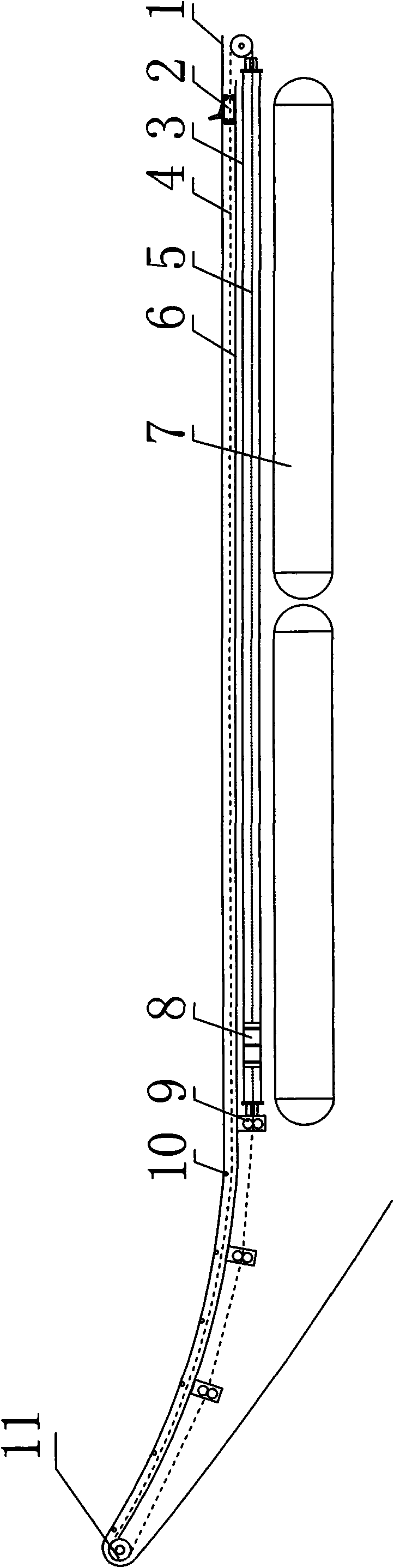
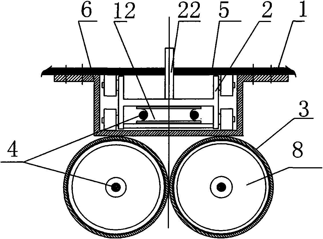
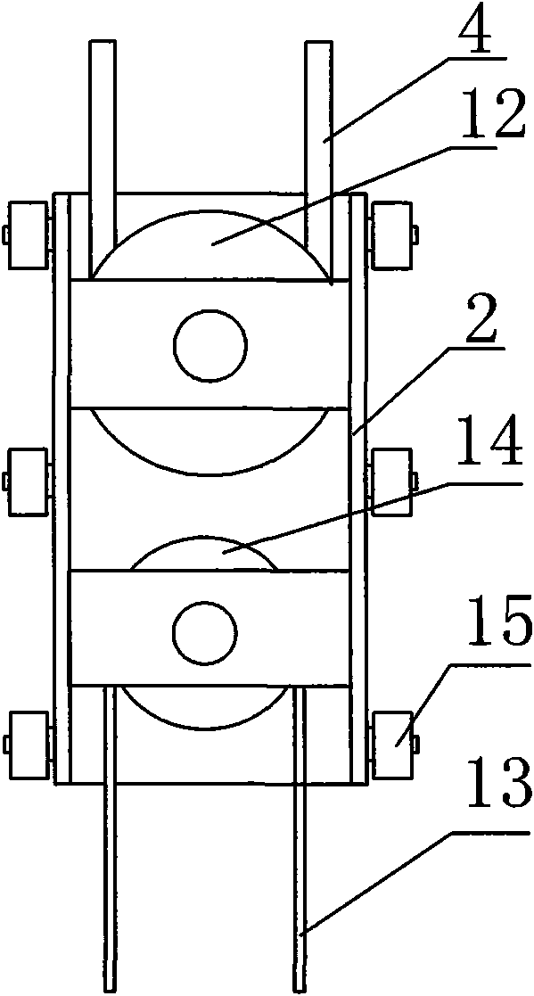
[0029] With reference to accompanying drawing, the steam catapult of aircraft carrier and its ejection method are described in detail below.

[0030] As shown in the accompanying drawings, the steam catapult for carrier-based aircraft of the present invention has a structure consisting of a take-off runway 1, a tackle 2, a tackle passage, a cylinder 3 and an ejection program controller, wherein the cylinder 3 is composed of Ejection cylinder 3 and damping cylinder 19 are composed, and damping cylinder 19 is connected to the end of piston ejection stroke, and the tackle channel is set in the middle of take-off runway 1, and tackle 2 is arranged in the tackle channel, and cylinder is arranged under the tackle channel, and the tackle 2 The bottom is provided with a traction cable balance pulley 12 and a return cable balance pulley 14, the middle of the traction cable 4 is wound on the traction cable balance pulley 12, and the two ends of the traction cable 4 pass through the cylin...


PUM


Abstract

The invention provides a steam catapult for a carrier-borne aircraft and a catapulting method thereof. The steam catapult comprises a take-off runway, a pulley, a pulley channel, a main traction winch, an auxiliary traction winch, a catapulting cylinder and a catapulting programmable controller, wherein the pulley channel is formed in the middle of an aircraft carrier ski-jump take-off runway or a horizontal take-off runway; the pulley is arranged in the pulley channel; the main traction winch and the auxiliary traction winch are arranged in a cabin below the take-off runway; the steel cables of the main traction winch and the auxiliary traction winch are connected with the front and rear ends of the pulley respectively; and the catapulting cylinder is arranged at the bottom of the pulley channel positioned at the starting point of the take-off runway. The catapult take-off of the carrier-borne aircraft is realized in pneumatic and mechanical traction modes, the defects that the conventional steam catapult has large volume, high energy consumption and short service life and is difficult to process are overcome, and a brand-new catapult for the carrier-borne aircraft is provided for aircraft carrier construction in China.

Description

technical field [0001] The invention relates to a catapult for military equipment or an aircraft carrier, in particular to a steam catapult for an aircraft carrier and an ejection method thereof. Background technique [0002] At present, the shortcomings of the steam catapult used by the US military are: the two cylinders of the steam catapult are open cylinders, the two pistons are fixed together, and the shuttle on the runway is directly driven by the hook on the piston , the ejection velocity is constant. The reset of the shuttle on the runway is completed by another set of steam-driven devices. Therefore, the equipment is bulky, occupies a large space, consumes a lot of energy, has high manufacturing costs, high operating costs, and high maintenance costs. Shuttle, so the shuttle connecting plate is set on two parallel pistons to protrude from the slotted cylinder of the 98.5-meter factory. Due to the existence of long slots, it not only increases the difficulty of cyli...

Claims


Application Information

Patent Timeline
IPC IPC(8): B64F1/06
Inventor 姜明
Owner 朱惠芬
Why Eureka
Try Eureka