Battery charging apparatus

A charging device and storage battery technology, applied in battery circuit devices, circuit devices, charging stations, etc., can solve problems such as maximum power limitation, and achieve the effect of realizing electric energy and realizing efficient utilization

Inactive Publication Date: 2011-09-28
SANYO ELECTRIC CO LTD
View PDF1 Cites 7 Cited by
  • Summary
  • Abstract
  • Description
  • Claims
  • Application Information

AI Technical Summary

Problems solved by technology

This is because the maximum power that can be used with a commercial power supply is limited.
For example, in a 200V single-phase commercial power supply, the maximum power that can be used is limited to about 5kW

Method used


Image

  • Battery charging apparatus
  • Battery charging apparatus
  • Battery charging apparatus

Examples


no. 1 approach

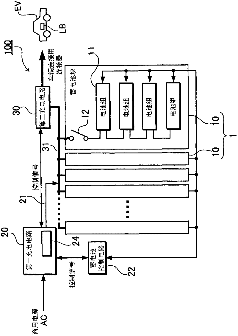
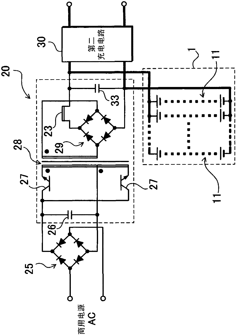
[0068] exist Figure 1 ~ Figure 2 The battery charging device according to the first embodiment 1 of the present invention is shown in . As shown in these figures respectively, figure 1 is a schematic diagram showing the storage battery charging device 100, figure 2 is shown figure 1 A circuit diagram of a circuit example of the first charging circuit 20. In this example, a power supply system that charges the parallel storage battery 1 and charges the externally connected load battery LB using a household commercial power supply AC is configured. Here, an example of charging a running battery of an automatic vehicle EV such as a plug-in hybrid vehicle or an electric vehicle as the load battery LB will be described. This storage battery charging device 100 includes a parallel storage battery 1, a first charging circuit 20 for charging the parallel storage battery 1 using a commercial power supply AC, a second charging circuit 30 for charging a load battery LB using the ...

no. 2 approach

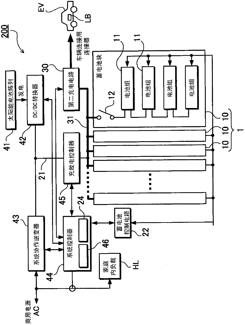
[0098] In the above example, although the example of using only the commercial power supply as the power source for charging is shown, the present invention is not limited to the above structure, and other power sources can be added instead of the commercial power supply or on the basis of it. source. For example, a current source using natural energy such as a solar cell, a fuel cell, a generator, and the like can be utilized. image 3 A power supply system using the battery charging device 200 according to the second embodiment is shown in . In this figure, the same symbols are attached to the components substantially the same as those of the first embodiment, and their detailed descriptions are omitted. Here, by combining the juxtaposed storage battery 1 in a household power supply system that installs a solar battery to drive a household load HL and sells power to a power company, the power of the solar battery is used for a load battery LB such as a vehicle running batte...


PUM


Abstract

The battery charging apparatus has an auxiliary battery, a first charging circuit for charging the auxiliary battery with a first charging current derived from an externally connected commercial power source AC, and a second charging circuit for charging the load battery LB with a second charging current that is higher than the first charging current and is derived from power from the auxiliary battery, which is charged by the first charging circuit. The first charging circuit is connected to allow power supply to the auxiliary battery and the second charging circuit. This makes charging circuit switching unnecessary and eliminates the need for components such as high-power switching devices. The charging apparatus has the positive features that stability and reliability are improved, and the load battery can be charged with the auxiliary battery in a shorter time than using commercial power.

Description

technical field [0001] The present invention relates to a charging device that uses a commercial power source to charge a load battery such as a running battery that is mounted on a vehicle and supplies power to an electric motor that drives the vehicle. Background technique [0002] With the spread of automatic vehicles such as electric vehicles that run on electric motors or hybrid cars that run on both electric motors and engines, chargers for charging the running batteries are required. In particular, in recent years, there has been an increasing demand for vehicles such as plug-in hybrid vehicles and electric vehicles equipped with batteries for driving that have a considerably larger number of batteries than hybrid vehicles, that is, a battery with a large capacity. , the capacity or charging capacity of the charger must also become larger. If it is attempted to charge such a large-capacity driving battery using a household commercial power supply, it takes a consider...

Claims


Application Information

Patent Timeline
Patent Type & Authority Applications(China)
IPC IPC(8): H02J7/02H02J7/10H02J7/00H02J7/34
CPCH02J7/0027Y02T10/7055H02J7/0055Y02T90/14B60L53/14B60L53/51H02J2207/40Y02T10/70Y02T10/7072Y02T90/12H02J7/0013H02J2310/48
Inventor 古川公彦平茂治板垣真一小路良浩宫崎晋也
Owner SANYO ELECTRIC CO LTD
Why Eureka
Try Eureka