
Flyback power converter

A power converter and flyback technology, which is applied in the direction of output power conversion device, AC power input conversion to DC power output, electrical components, etc., can solve the problem of reducing the size and manufacturing cost of flyback power converters, Does not eliminate the problems of optocoupler and secondary feedback circuit, increase manufacturing cost, etc., achieves the effect of shortening the design cycle, reducing external components, and simplifying the structural design

Inactive Publication Date: 2011-09-28
深圳市展芯微电子技术有限公司
View PDF2 Cites 14 Cited by
  • Summary
  • Abstract
  • Description
  • Claims
  • Application Information

AI Technical Summary

Problems solved by technology

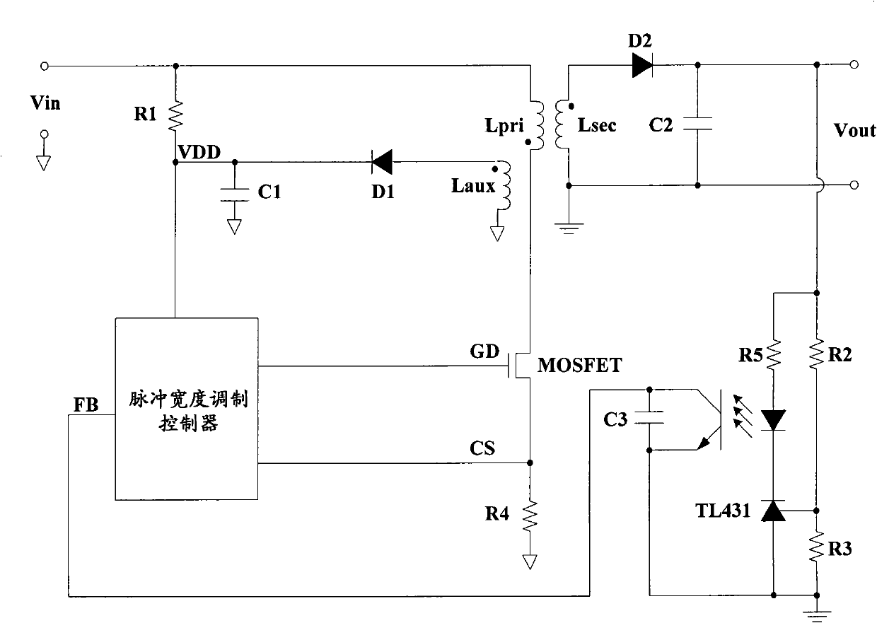
Although this structure has high output accuracy and dynamic adjustment rate, more external components (especially optocouplers and voltage regulators) virtually occupy more space and increase manufacturing costs
[0004] In the prior art, it is difficult to reduce the size and manufacturing cost of the flyback power converter without eliminating the optocoupler and the secondary feedback circuit

Method used


Image

  • Flyback power converter
  • Flyback power converter
  • Flyback power converter

Examples


Embodiment Construction

[0035] In order to make the object, technical solution and advantages of the present invention more clearly, the present invention will be further described in detail below in conjunction with specific examples.

[0036] At first, the technical term of the present invention is explained:

[0037] MOSFET: Metal Oxide Semiconductor FET, Metal Oxide Semiconductor Field Effect Transistor;

[0038] PWM: Pulse Width Modulation, pulse width modulation;

[0039] PFM: Pulse Frequency Modulation, pulse frequency modulation;

[0040] DCM: Discontinuous Conduction Mode, discontinuous (discontinuous) conduction mode;

[0041] CCM: Continuous Conduction Mode, continuous conduction mode.

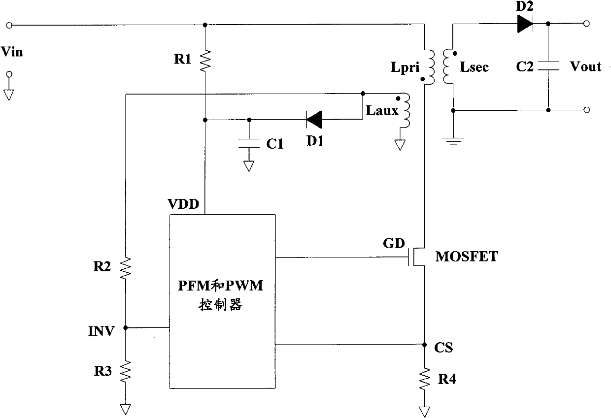
[0042] Such as figure 2 As shown, it is a schematic circuit diagram of a flyback power converter in an embodiment of the present invention. The flyback power converter includes: a transformer, a first rectifier D1, a second rectifier D2, a first capacitor C1, a second Capacitor C2, first resistor R1,...


PUM


Abstract

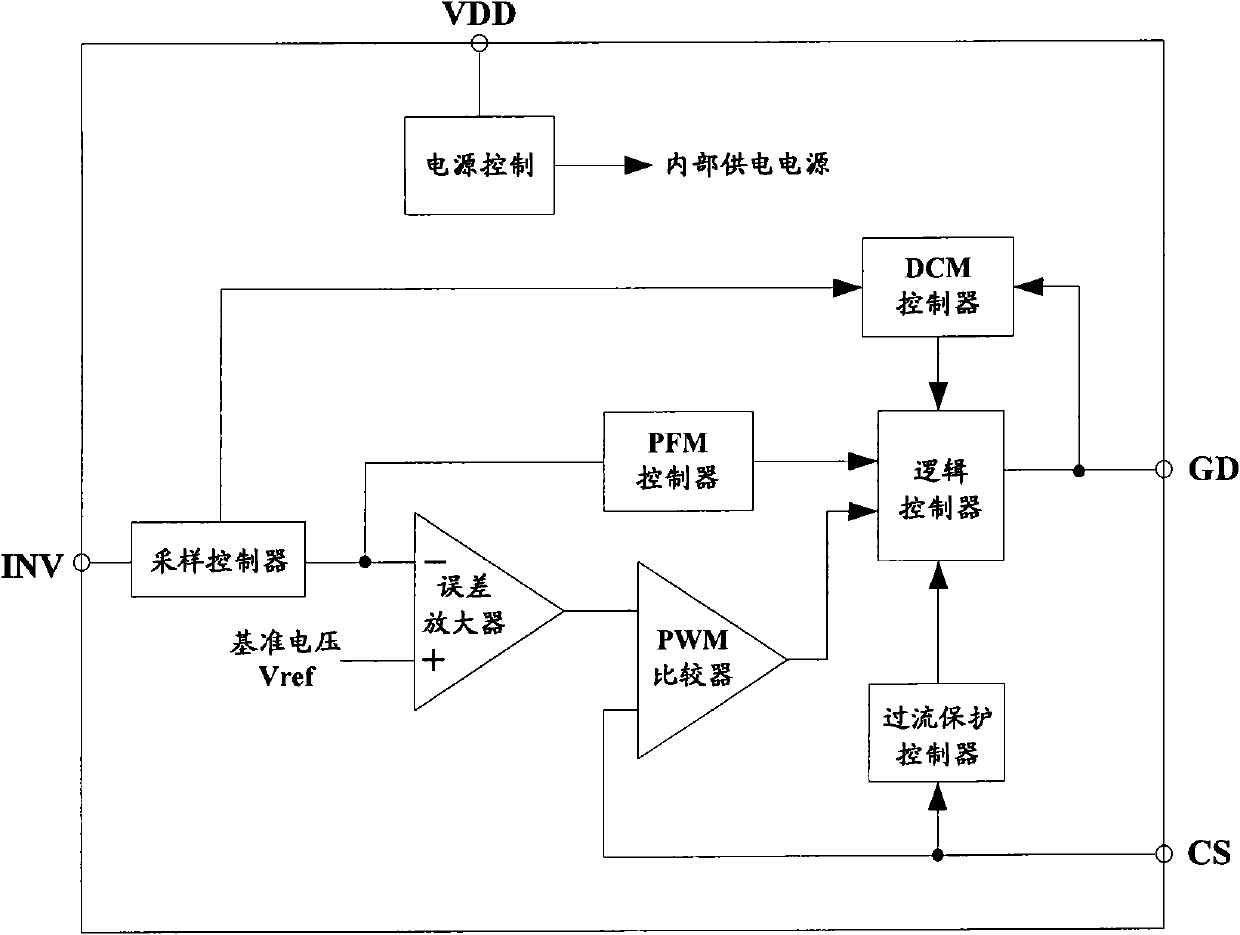
The invention provides a flyback power converter, which comprises a transformer, a first rectifier, a second rectifier, a first capacitor, a second capacitor, a first resistor, a second resistor, a third resistor, a fourth resistor, a switch transistor and a pulse frequency modulation and a pulse width modulation controller, wherein the pulse frequency modulation and a pulse width modulation controller is used for providing a control signal to drive the grid of the switch transistor; the transformer comprises a primary winding, a secondary winding and an auxiliary winding; one end of the primary winding is connected with the power supply input end of the flyback power converter, and the other end of the primary winding is connected with the drain of the switch transistor; the switch transistor is used for controlling the voltage of the primary winding; one end of the secondary winding is grounded, and the other end of secondary winding is connected with the anode of the secondary rectifier; and one end of the auxiliary winding is grounded, and the other end of the auxiliary winding is connected with one end of the secondary resistor. The structure of the flayback power converter can be effectively simplified.

Description

technical field [0001] The invention relates to a switch-mode flyback power converter, in particular to a flyback power converter based on transformer primary side sampling. Background technique [0002] As an important part of switching power supply, the flyback power converter is widely used in many fields such as battery chargers and power adapters. A flyback power converter typically includes a pulse-width modulation controller, switching MOSFETs (metal-oxide-semiconductor field-effect transistors), a transformer, and a feedback control circuit. The purpose of the feedback control circuit is to sense the voltage or current at the secondary output terminal of the transformer, and send the feedback signal to the pulse width modulation controller through an isolation device (such as an optocoupler), so as to stabilize the output voltage or current. With the continuous development of society, the existing flyback power converters are more and more focused on the research of...

Claims


Application Information

Patent Timeline
Patent Type & Authority Applications(China)
IPC IPC(8): H02M7/217
Inventor 夏云凯雷晗
Owner 深圳市展芯微电子技术有限公司
Learn More