

Flyback power converter
A power converter and flyback technology, which is applied in the direction of output power conversion device, AC power input conversion to DC power output, electrical components, etc., can solve the problem of reducing the size and manufacturing cost of flyback power converters, Does not eliminate the problems of optocoupler and secondary feedback circuit, increase manufacturing cost, etc., achieves the effect of shortening the design cycle, reducing external components, and simplifying the structural design
- Summary
- Abstract
- Description
- Claims
- Application Information
AI Technical Summary
Problems solved by technology
Method used
Image

Examples
Embodiment Construction
[0035] In order to make the object, technical solution and advantages of the present invention more clearly, the present invention will be further described in detail below in conjunction with specific examples.
[0036] At first, the technical term of the present invention is explained:
[0037] MOSFET: Metal Oxide Semiconductor FET, Metal Oxide Semiconductor Field Effect Transistor;
[0038] PWM: Pulse Width Modulation, pulse width modulation;
[0039] PFM: Pulse Frequency Modulation, pulse frequency modulation;
[0040] DCM: Discontinuous Conduction Mode, discontinuous (discontinuous) conduction mode;
[0041] CCM: Continuous Conduction Mode, continuous conduction mode.
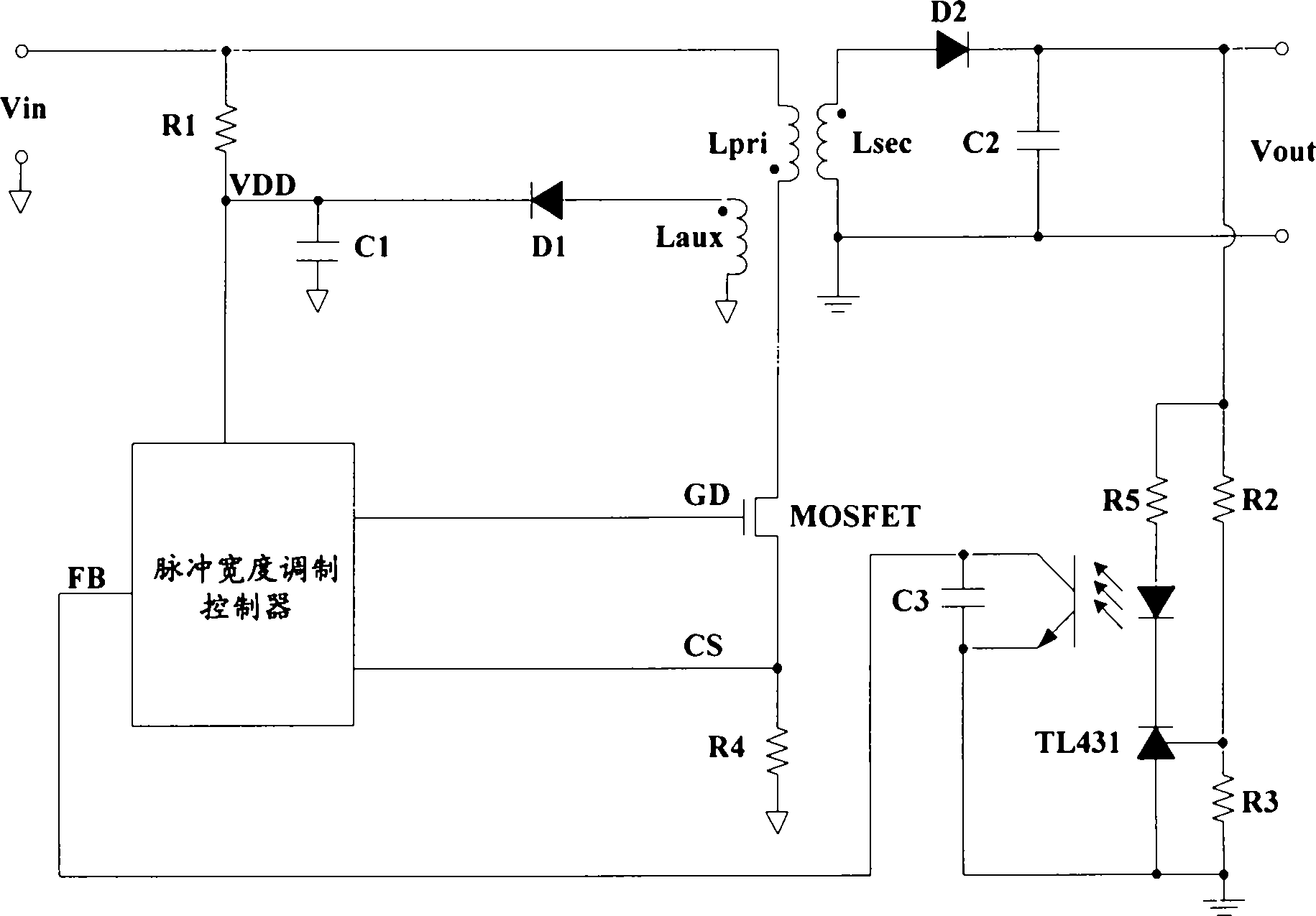
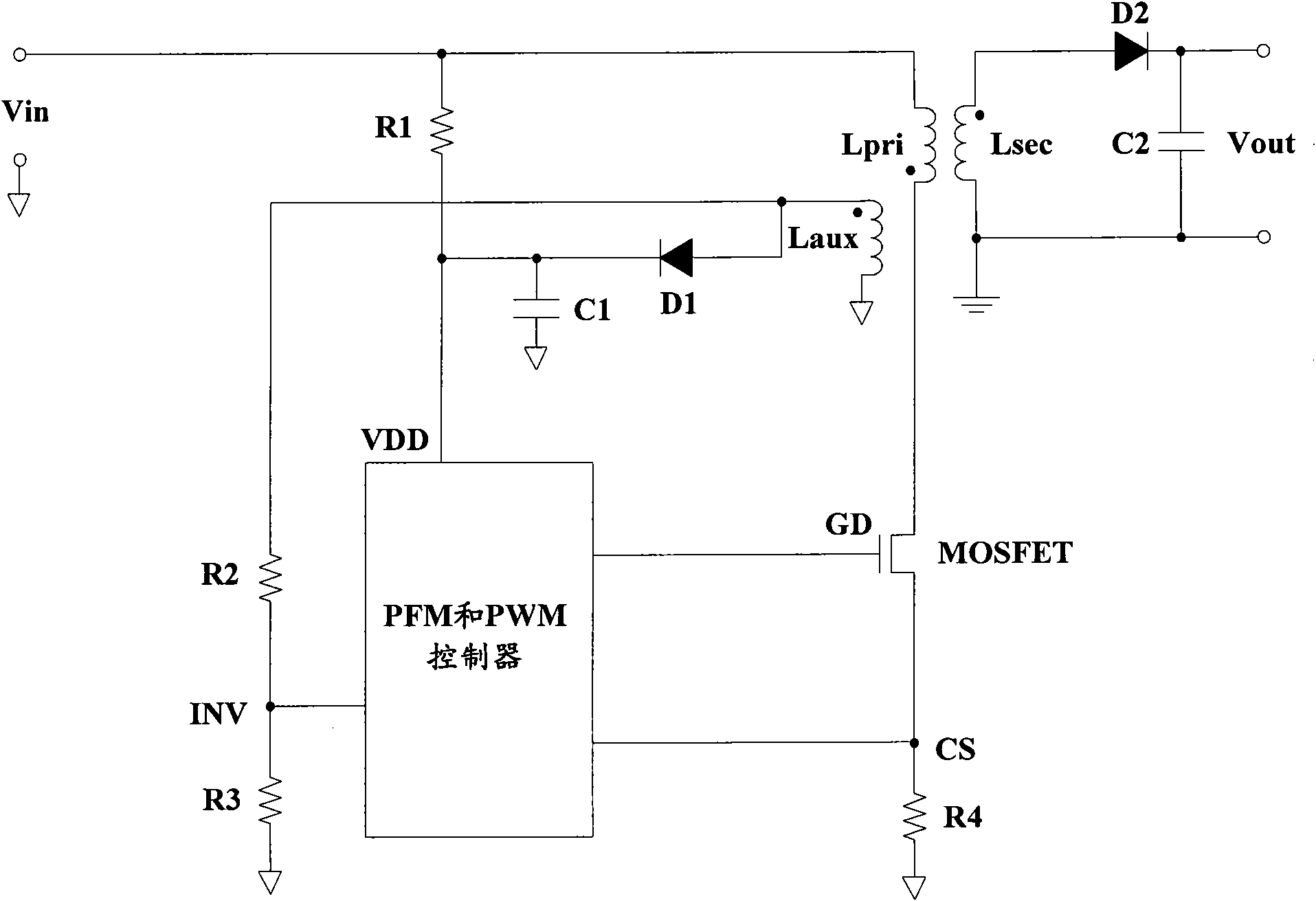
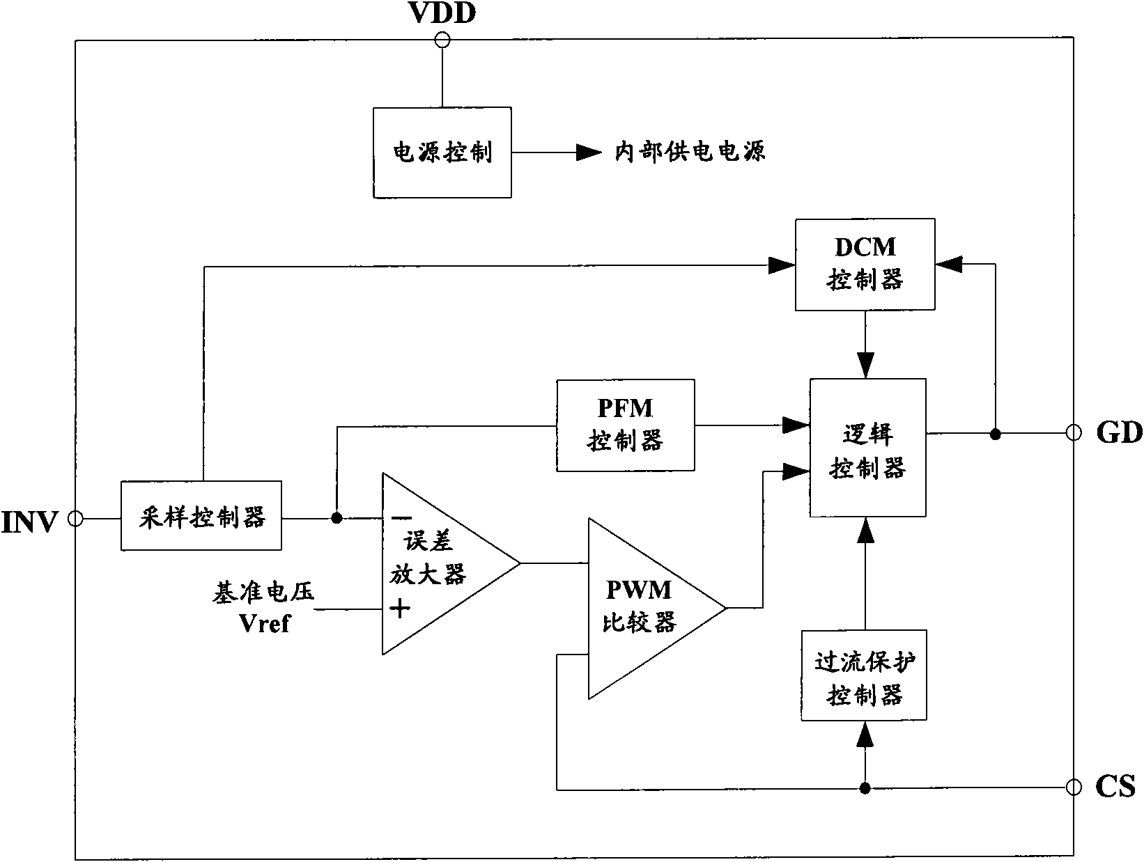
[0042] Such as figure 2 As shown, it is a schematic circuit diagram of a flyback power converter in an embodiment of the present invention. The flyback power converter includes: a transformer, a first rectifier D1, a second rectifier D2, a first capacitor C1, a second Capacitor C2, first resistor R1,...
PUM
 Abstract
Description
Claims
Application Information