Supercharge Your Innovation With Domain-Expert AI Agents!

Cylindrical battery

A technology for cylindrical batteries and pole groups, which is applied in secondary batteries, battery components, secondary battery manufacturing, etc., and can solve the problem of high current charging and discharging performance, battery heat dissipation performance needs to be improved, and tabs or connectors are hot and red. , Large-capacity battery heat dissipation difficulties and other issues, to achieve excellent high-current charge and discharge performance and safety performance, improve internal heat dissipation performance, and improve the effect of heat dissipation

Active Publication Date: 2013-06-26
先进储能材料国家工程研究中心有限责任公司
View PDF4 Cites 0 Cited by
  • Summary
  • Abstract
  • Description
  • Claims
  • Application Information

AI Technical Summary

Problems solved by technology

[0002] At present, due to the global energy shortage and the strengthening of environmental protection awareness, electric vehicle batteries and energy storage batteries are hot in the market, and large-capacity secondary batteries (nickel-metal hydride, nickel-cadmium, lithium batteries, lead-acid, etc.) on the market generally adopt rectangular structures. Especially Ni-MH batteries, which are larger than 20Ah, adopt a rectangular structure. The reason is that it is difficult to dissipate heat inside a large-capacity battery, which is likely to cause thermal runaway
However, the inherent defects of the rectangular secondary battery cannot fully meet the market demand, and the high-current charge and discharge performance of the existing cylindrical secondary battery and the heat dissipation performance of the internal heat of the battery need to be improved.
Moreover, the positive and negative electrode sheets of the existing secondary battery are connected to the lead-out ends by welding the tabs, and there are welding points and welded connectors. When the current is high or the battery is short-circuited, the tabs or the connectors will be hot and red. , so as to cause serious safety accidents such as battery burning

Method used


Image

  • Cylindrical battery
  • Cylindrical battery

Examples


Embodiment Construction

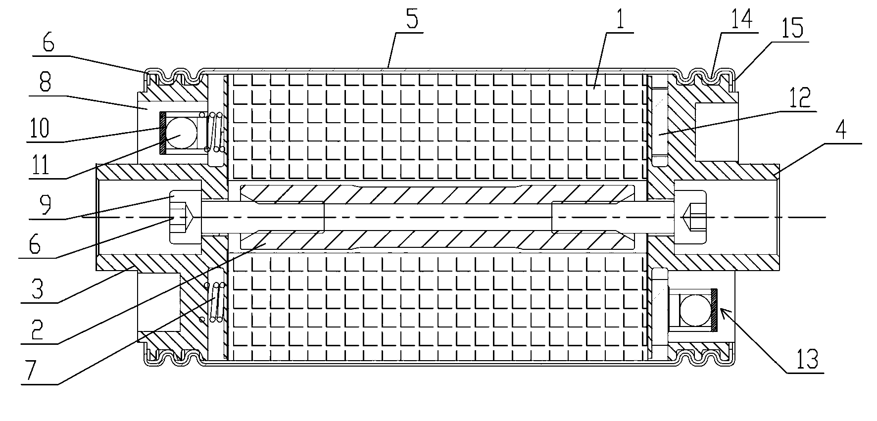
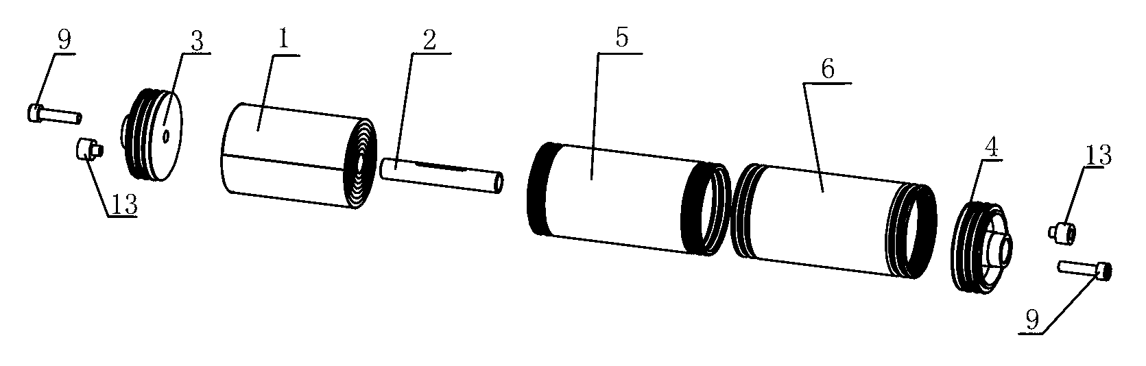
[0018] Such as figure 1 with figure 2 As shown, the cylindrical battery of the present invention includes a cylindrical battery electrode group 1 wound from a positive electrode sheet and a negative electrode sheet separated by a separator, and the cylindrical battery electrode group 1 is wound on a mandrel 2; The cylindrical battery pole group 1 is installed in the casing 5, and the casing 5 is lined with an insulating rubber sleeve 6; The entire end of the positive electrode sheet at the opposite end is connected, and the inner end surface of the negative electrode lead-out end 4 at the other end of the cylindrical battery electrode group 1 is directly connected to the entire end of the negative electrode sheet at the opposite end of the cylindrical battery electrode group 1, thereby Consisting of a non-welded surface contact confluence structure with the positive terminal and the negative terminal respectively arranged at both ends of the battery.

[0019] see figure 1 ...


PUM


Abstract

Provided is a cylindrical battery, comprising a cylindrical battery electrode assembly which is formed by coiling a positive plate and a negative plate separated by a diaphragm and is coiled on a core bar. The cylindrical battery is characterized in that an inner end face of a positive electrode lead-out terminal located at one end of the cylindrical battery electrode assembly is directly connected with the entire end of the positive plate at the corresponding end of the cylindrical battery electrode assembly, and an inner end face of a negative electrode lead-out terminal located at the other end of the cylindrical battery electrode assembly is directly connected with the entire end of the negative plate at the corresponding end of the cylindrical battery electrode assembly, so that a bus structure is formed in such a manner that the positive and negative electrode lead-out ends are respectively configured at two ends of the battery. In the invention, as the positive and negative electrodes are respectively arranged at two ends of the battery, current of the positive and negative plates flows from the two ends, significantly increasing the high current charge-discharge capability of the battery and effectively improving the performance of heat dissipation in the battery as well as the safety property of the battery.

Description

technical field [0001] The present invention relates to a secondary battery, and further refers to a cylindrical secondary battery. Background technique [0002] At present, due to the global energy shortage and the strengthening of environmental protection awareness, electric vehicle batteries and energy storage batteries are hot in the market, and large-capacity secondary batteries (nickel-metal hydride, nickel-cadmium, lithium batteries, lead-acid, etc.) on the market generally adopt rectangular structures. Especially nickel-metal hydride batteries, which are larger than 20Ah, adopt a rectangular structure. The reason is that it is difficult to dissipate heat inside a large-capacity battery, which is likely to cause thermal runaway. However, the inherent defects of the secondary battery with a rectangular structure cannot fully meet the market demand, and the high-current charge and discharge performance of the existing cylindrical secondary battery and the heat dissipati...

Claims


Application Information

Patent Timeline
Patent Type & Authority Patents(China)
IPC IPC(8): H01M2/06H01M2/26H01M50/167H01M50/179H01M50/536H01M50/538
CPCY02E60/12H01M10/5051H01M2/1229H01M10/5046H01M10/5004H01M10/0431H01M10/503H01M2/06H01M2/263H01M2/0413H01M10/6553H01M10/6551H01M10/643H01M10/613Y10T29/49108Y02E60/10H01M50/171H01M50/325H01M50/538Y02P70/50H01M50/536H01M50/179H01M50/167
Inventor 钟发平何策衡陈风
Owner 先进储能材料国家工程研究中心有限责任公司
Features
  • R&D
  • Intellectual Property
  • Life Sciences
  • Materials
  • Tech Scout
  • Unparalleled Data Quality
  • Higher Quality Content
  • 60% Fewer Hallucinations
Learn More