Low-heating-value gas burner

A low calorific value gas and burner technology, applied in the direction of gas fuel burners, burners, combustion methods, etc., can solve the problems of low flame temperature, inability to burn low calorific value gas, and unstable combustion, etc., to achieve safe operation and occupy space Effects of small, expensive equipment

Active Publication Date: 2011-10-05
安徽绿宝不锈钢设备制造有限公司
View PDF4 Cites 10 Cited by
  • Summary
  • Abstract
  • Description
  • Claims
  • Application Information

AI Technical Summary

Problems solved by technology

[0004] The object of the present invention is to provide a low calorific value gas burner, which can solve the shortcomings of traditional burners such as inability to burn low calorific value gas, low flame temperature, and unstable combustion.

Method used


Image

  • Low-heating-value gas burner
  • Low-heating-value gas burner
  • Low-heating-value gas burner

Examples


Embodiment 1

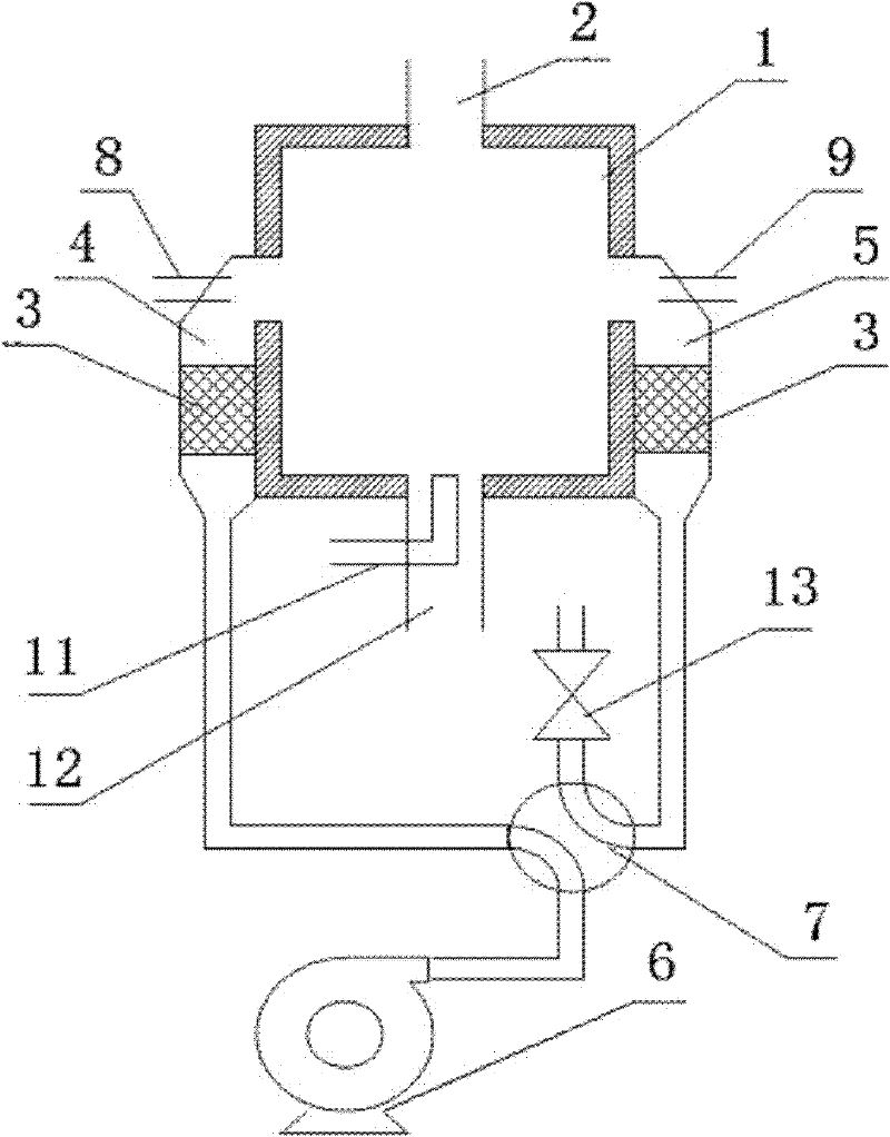
[0028] Example 1: Combining figure 1 As shown, it is a preferred embodiment of a low calorific value gas burner, which consists of a combustion chamber 1, a single heat storage device, a main gas delivery device (not shown in the figure), a main air delivery device (not shown in the figure) ) and a high temperature exhaust device (not shown in the figure). The top of the combustion chamber 1 is provided with a high-temperature gas outlet 2, and the high-temperature gas outlet 2 is connected with a high-temperature exhaust device through a pipeline; At the same time, a main gas nozzle 11 and a main air nozzle 12 are provided, which are respectively connected with the main gas delivery device and the main air delivery device through pipelines.

[0029]The alternate heat storage device in this embodiment consists of the left and right regenerators 4, 5 symmetrically distributed on both sides of the combustion chamber 1, the left and right gas nozzles 8, 9, the air delivery devic...

Embodiment 2

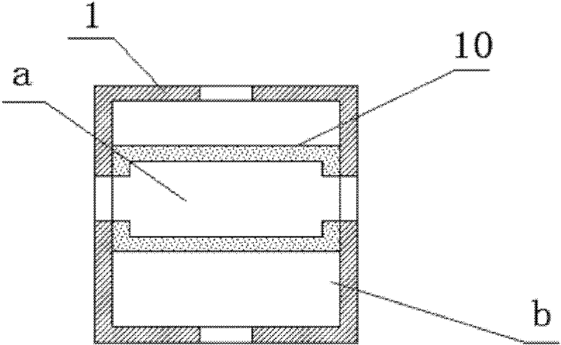
[0037] In this embodiment, two alternate heat storage devices are used, that is, four heat storage chambers are arranged on the side of the combustion chamber 1, so that when the two heat storage chambers 4 and 5 in one alternate heat storage device are 7. When reversing, the two regenerators in the other alternate heat storage device can continuously and stably alternately work in the heat storage and heat release states, so as to ensure that the pressure field and temperature field in the combustion chamber 1 will not be too large. Large fluctuations, maintaining the stability of high temperature outlet gas temperature and flow.

[0038] Others of this embodiment are the same as Embodiment 1.

Embodiment 3

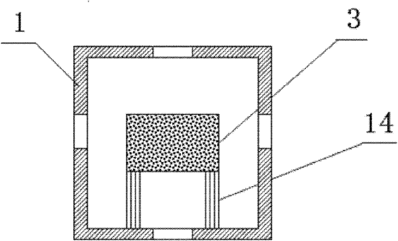
[0040] In the present embodiment, the gas nozzles 8 and 9 on the left and right sides are not provided, and the gas is all sent in through the bottom of the combustion chamber 1 . That is, at the initial stage, the main gas nozzle 11 injects low calorific value coal gas and combusts the air blown in from the left and right regenerators 4 and 5. At this time, the high-temperature gas outlet 2 is closed, and the left and right regenerators 4 and 5 are reversing in four directions. Under the action of the valve 7, it operates alternately. After the combustion chamber 1 reaches the set high temperature (1200°C), the flow rate of the main gas nozzle 11 is increased and the main air nozzle 12 and the high-temperature gas outlet 2 are opened at the same time. The high-temperature gas is discharged from the high-temperature gas outlet 2. Discharged for heating and calcination.

[0041] Others of this embodiment are the same as Embodiment 1.


PUM


Abstract

The invention discloses a low-heating-value gas burner which comprises a burning chamber, wherein the top of the burning chamber is provided with a high-temperature gas outlet and the bottom of the burning chamber is provided with an air / gas inlet through which air and gas can enter simultaneously. The low-heating-value gas burner is characterized by also comprising at least one alternative heat storage device, each heat storage device comprises two heat storage chambers which are respectively and internally provided with a heat accumulator, a heat accumulating air conveyor, a low-temperature exhausting device and a four-way reversing valve; a ventilating hole connected with the two heat storage chambers is arranged on the side of the burning chamber; and the two heat storage chambers, the heat accumulating air conveyor and the low-temperature exhausting device are all connected with four connectors of the four-way reversing valve through pipelines. The low-heating-value gas burner disclosed by the invention can overcome the defects of incapability of burning low-heating-value gas, low flame temperature, unstable burning and the like.

Description

technical field [0001] The invention belongs to the technical field of combustion equipment, in particular to a low calorific value gas burner. Background technique [0002] "Experimental Research on High-Temperature Air Regenerative Combustion" (Northeastern University, Jiang Honglin, Master Thesis) summarizes the development of high-temperature air combustion technology and the working principle of high-temperature and low-oxygen regenerative burners. The type burner is a pair of burners with regenerators. Under the control of the automatic reversing system, the burners can achieve precise timing and temperature reversing work. The burners must appear in pairs and be installed on the kiln. When working, one burner burns, and the other burner acts as a recovery device for flue gas heat. After a period of time, the two burners switch working states, and a reversing valve is used to change the direction of air and flue gas flow. [0003] "International Development Trends of...

Claims


Application Information

Patent Timeline
Patent Type & Authority Applications(China)
IPC IPC(8): F23D14/00F23D14/46F23D14/66
CPCY02E20/34
Inventor 徐正前林其钊张海涛秦向东
Owner 安徽绿宝不锈钢设备制造有限公司
Why Eureka
Try Eureka