
Liquid-solid fluidized bed microbial fuel cell hydrogen production device

A fuel cell and fluidized bed technology, which is applied in the field of electric-assisted hydrogen production in liquid-solid fluidized bed reactor biofuel cells, can solve the problems of low mass transfer efficiency, uneven distribution of microorganisms, and difficult industrial scale-up of sewage treatment, etc., to achieve High volume power density, accelerated biochemical reaction rate, improved effect and hydrogen production effect

Inactive Publication Date: 2013-06-12
QINGDAO UNIV OF SCI & TECH
View PDF2 Cites 0 Cited by
  • Summary
  • Abstract
  • Description
  • Claims
  • Application Information

AI Technical Summary

Problems solved by technology

Anaerobic fluidized bed anode microbial fuel cell is a new type of reactor that integrates microbial fuel cell hydrogen production technology with fluidized bed reactor, and belongs to the technical solution that researchers in this technical field are waiting to develop and innovate; and The ordinary battery (MFC) in the prior art is mostly suitable for laboratory research, and the anode is mostly used for stirring, which has outstanding shortcomings such as uneven distribution of microorganisms, low mass transfer efficiency, and difficulty in industrial scale-up of sewage treatment.

Method used


Image

  • Liquid-solid fluidized bed microbial fuel cell hydrogen production device
  • Liquid-solid fluidized bed microbial fuel cell hydrogen production device
  • Liquid-solid fluidized bed microbial fuel cell hydrogen production device

Examples


Embodiment

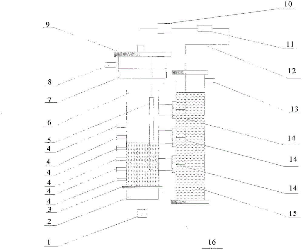
[0011] The main structure of this embodiment includes a sewage inlet 1, a pre-distribution chamber 2, a liquid distribution plate 3, a test port 4, an anode electrode 5, an anode fluidized bed body 6, a fluidized bed expansion section 7, a sewage outlet 8, and a sealing cover 9 , stabilized power supply 10, load 11, wire 12, gas collection outlet 13, cathode 14, cathode chamber 15 and fluidized particles 16, each component is combined to form an anaerobic fluidized bed membrane cathode microbial fuel cell device; sewage inlet 1 is located in the reaction The central position of the bottom of the device, the pipe diameter is Φ15mm; the sewage outlet 8 is located at the side wall of the anode fluidized bed body 6 50mm from the top, the pipe diameter is Φ15mm; the diameter of the pre-distribution chamber 2 is 40mm, and it is connected to the anode fluidized bed body 6 through the flange Connect; liquid distribution plate 3 opening diameter Φ1.5-2.5mm, opening ratio 10-15%, guarant...


PUM

PropertyMeasurementUnit
diameteraaaaaaaaaa
diameteraaaaaaaaaa
particle diameteraaaaaaaaaa

Abstract

The invention belongs to the technical field of battery hydrogen production, and relates to a liquid-solid fluidized bed microbial fuel cell hydrogen production device. The bottom center of the device is provided with a sewage inlet, a sewage outlet is formed at the top of the side wall of an anode fluidized bed, and the upper part of the sewage inlet is provided with a pre-distribution chamber and connected with the anode fluidized bed through a flange; a liquid distribution plate is arranged between the pre-distribution chamber and the anode fluidized bed, and fluidized granules are filled in the inner lower part of the anode fluidized bed; a positive electrode of a graphite carbon rod is vertically placed inside the anode fluidized bed, one end of the bottom of the positive electrode is inserted into the fluidized granules, and the other end of the positive electrode and a carbon paper membrane cathode are connected through a welding lead and connected in series with a load and a stabilized voltage supply to form a closed loop; and 2 to 10 test ports are arranged vertically on the lower middle part of the side wall of the anode fluidized bed of organic glass in equal distance, and the side wall of the top of a cathode chamber is provided with a gas collecting outlet. The device has the advantages of low battery cost, high power generation performance, wide operating area, reliability in operation and good mass transfer effect of the anaerobic fluidized bed.

Description

Technical field: [0001] The invention belongs to the technical field of liquid-solid fluidized bed reactor biological fuel cell electric auxiliary hydrogen production, and relates to a liquid-solid fluidized bed microbial fuel cell hydrogen production device, which integrates a liquid-solid fluidized bed and microbial fuel for wastewater treatment occasions , especially suitable for beer industry wastewater, food processing wastewater, urban domestic sewage and other organic sewage treatment occasions. Background technique: [0002] At present, the energy crisis and environmental pollution have become increasingly serious, threatening the survival and development of human beings. Developing renewable energy and taking the road of sustainable development has become the focus of research by scholars from all over the world. However, due to the intermittency and difficulty in storage and transportation of renewable energy such as solar energy and wind energy, an efficient and ...

Claims


Application Information

Patent Timeline
Patent Type & Authority Patents(China)
IPC IPC(8): H01M8/06C02F3/28C01B3/02
CPCY02E60/50Y02W10/33Y02W10/37
Inventor 王许云郭庆杰赵书菊岳学海孔维芳
Owner QINGDAO UNIV OF SCI & TECH
Learn More