Method and system of virtual machine migration

一种迁移系统、虚拟机的技术,应用在动态迁移领域,能够解决用户感觉不到迁移等问题,达到减少停机时间的效果

Inactive Publication Date: 2011-10-05
HITACHI LTD
View PDF4 Cites 44 Cited by
  • Summary
  • Abstract
  • Description
  • Claims
  • Application Information

AI Technical Summary

Problems solved by technology

In Non-Patent Document 1, it is described that the downtime of a VM executing an online game such as Quake3 has been successfully suppressed to 60 ms, and as a result, the user hardly feels the migration

Method used


Image

  • Method and system of virtual machine migration
  • Method and system of virtual machine migration
  • Method and system of virtual machine migration

Examples


Embodiment 1

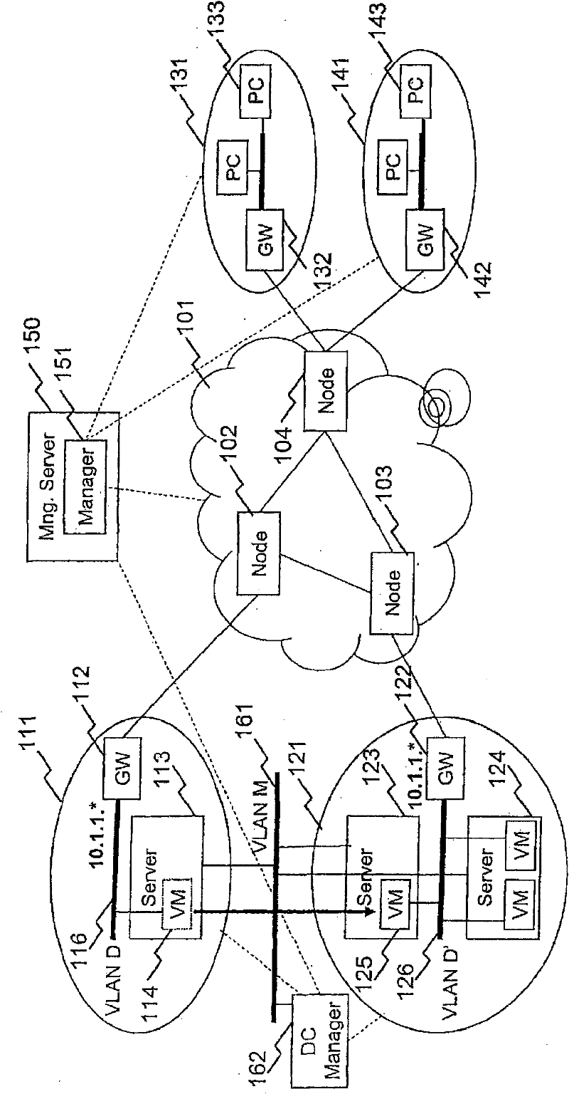
[0042] figure 1 It is a physical configuration diagram of the network shared by the first and second embodiments.

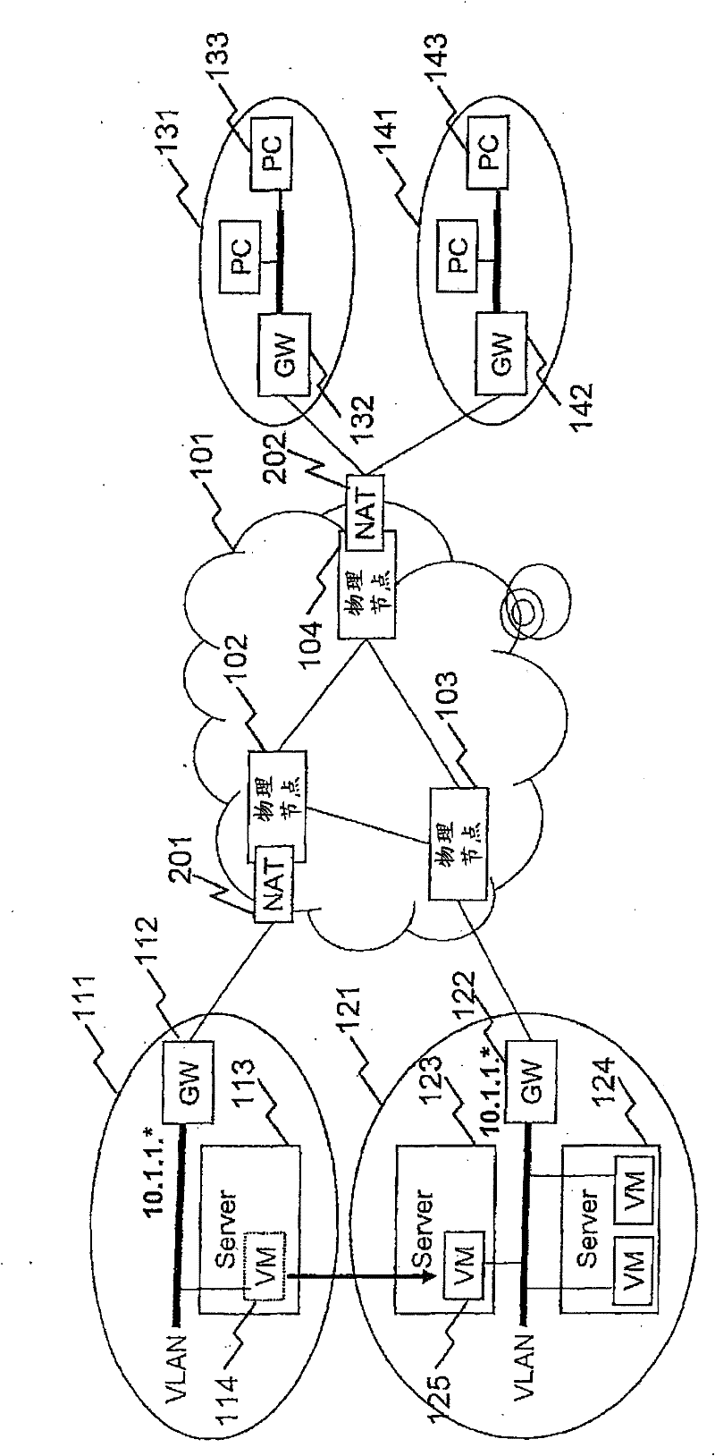
[0043] In this figure, the central first network, WAN 101, includes: an edge node (Node) 102 connected to a data center 111; an edge node 103 connected to a data center 121; and networks 131 and 141 for users that constitute the second network. connected edge nodes 104 . WAN 101 may also include more network nodes. In addition, multiple network nodes may also be connected to different user networks. The edge nodes 102, 103, and 104 are routers having a Network Address Translation (NAT) function in the first embodiment, and layer 3 (L3) devices having a network virtualization function in a second embodiment described later. switch.

[0044] In WAN 101 , instead of directly connecting edge nodes, they may be connected via core nodes. In addition, the networks 131 and 141 of users constituting the second network may not be connected to the same edge node 104, b...

Embodiment 2

[0112] Next, use Figure 6 The outline of the second embodiment will be described. exist Figure 6 In the second embodiment shown, WAN 101 is virtualized, creating two virtual networks 601A and 601B. The topology of these virtual networks is the same as the physical network 101 . That is, virtual network 601A includes virtual node 602A corresponding to physical node 102 , virtual node 603A corresponding to physical node 103 , and virtual node 603A corresponding to physical node 103 . In addition, the virtual network 601B includes a virtual node 602B corresponding to the physical node 102 , a virtual node 603B corresponding to the physical node 103 , and a virtual node 603B corresponding to the physical node 103 .

[0113] Packets on virtual network 601A and virtual network 601B coexist on physical network 101 , but which virtual network they belong to is identified by an identifier on the packet, a wavelength in a used optical path, a used line (path), and the like. As the...


PUM


Abstract

The invention provides a method and a system of virtual machine migration. In cooperation between each data center and a WAN, virtual machine migration is carried out without interruption in processing so as to enable effective power-saving implementation, load distribution, or fault countermeasure processing. Each node located (102, 104) at a boundary point between the WAN (101) and another network (111, 131, 141) is provided with a network address translation (NAT, 201, 202) function that can be set dynamically to avoid address duplication due to virtual machine migration. Alternatively, each node (102, 103, 104) included in the WAN (101) is provided with a network virtualization function; and there are implemented a virtual network connected to a data center (111) for including a virtual machine before migration, and a virtual network connected to a data center (121) for including the virtual machine after migration, thereby allowing coexistent provision of identical addresses. Thus, the need for changing network routing information at the time of virtual machine migration (114, 125) can be eliminated, and a setting change for migration accomplished quickly.

Description

technical field [0001] The present invention relates to the dynamic migration technology of virtual machines between servers at different locations on the network. Background technique [0002] The traffic volume on the Internet is gradually increasing. Along with this, the power consumption of the entire network continues to increase. On the other hand, for the solution of the global warming problem including the suppression of carbon dioxide emission, the importance of energy conservation has increased. Conventional technology has achieved energy saving in each data center and each network node, but in order to achieve more effective energy saving, it is very important to cooperate with these data centers and a wide area network (Wide Area Network: WAN). One reason for this is that if communication traffic between a certain data center and users and other servers is completely eliminated, the network nodes prepared for the communication can also be powered off at the sam...

Claims


Application Information

Patent Timeline
Patent Type & Authority Applications(China)
IPC IPC(8): H04L12/56H04L12/46H04L29/12G06F9/46G06F9/50G06F11/20
CPCH04L49/70H04L29/12028H04L49/557H04L61/103H04L29/12367H04L29/12264G06F9/4856H04L12/4641Y02B60/162H04L61/2046H04L61/2514G06F11/1484Y02B60/144H04L45/00Y02D10/00H04L61/5046H04L45/76
Inventor 金田泰春日井靖铃木慎治垂井俊明
Owner HITACHI LTD
Why Eureka
Try Eureka