Quality control method for solder joint portion and quality control device

A technology for solder joints and quality management, which is applied in the direction of assembling printed circuits, electrical components, electrical components, etc., can solve the problem of soldering that is not suitable for mass production of multiple pins and narrow spacing, manual operation volatility, Problems such as low productivity

Inactive Publication Date: 2013-12-04
MITSUBISHI ELECTRIC CORP
View PDF5 Cites 0 Cited by
  • Summary
  • Abstract
  • Description
  • Claims
  • Application Information

AI Technical Summary

Problems solved by technology

[0004] As a representative example of such a local heating mounting method, a soldering iron method in which a solder wire and a high-temperature soldering iron are supplied to the above-mentioned joint portion and bonded is widely used, but low productivity and fluctuations in manual work are problems, and it is not suitable for this method. Soldering of multi-pin, narrow-pitch, mass-produced components

Method used


Image

  • Quality control method for solder joint portion and quality control device
  • Quality control method for solder joint portion and quality control device
  • Quality control method for solder joint portion and quality control device

Examples


Embodiment approach 1

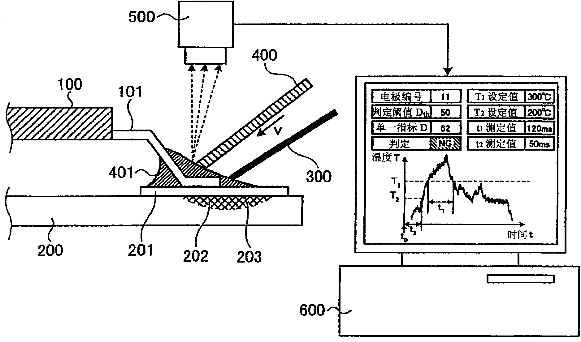
[0030] figure 1 It is a figure which shows the state in which the laser soldering of Embodiment 1 concerning this invention is joining. Component terminals 101 of electronic component 100 are bonded to substrate terminals 201 of resin substrate 200 via solder 401 . At a predetermined timing, a solid welding wire 400 (the feeding mechanism of the welding wire 400 is not shown) is supplied to the junction at a speed v (function of time), and at the same time, a laser beam 300 (laser beam 300) as a thermal energy supply source is supplied with a power p (function of time). Beam irradiation source, positioning mechanism, etc. are not shown in the figure). Such as figure 1 As shown, by locally supplying thermal energy, the temperature rise of the electronic component 100 can be suppressed.

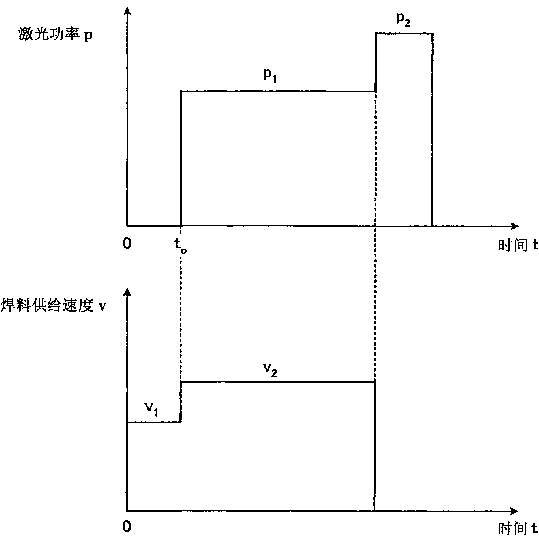
[0031] figure 2 It is a figure which shows an example of the joining condition curve of wire supply speed v and laser power p. The bonding conditions are based on the heat capacity of the...


PUM


Abstract

The invention provides a quality control method for solder a joint portion, enabling highly accurate quality inspection in a non-damaged manner at a real time bases without an extra inspection process. The quality control method for a joint portion formed when solder and partial heat energy are supplied to a resin substrate, includes measuring temperature of the joint portion varying with time during jointing process, calculating a plurality of characteristic values based on the measured values, obtaining a single value index based on the plurality of characteristic values, and determining whether the joint portion is qualified or not by comparing the value index with the predetermined threshold, wherein the characteristic values includes time t1 indicating the time when the temperature of the joint portion is higher or equal to the predetermined time T1 which satisfied the conditions of (substrate vitrification temperature- 50 DEG C) <= T1<= (substrate vitrification temperature+250 DEG C), and time t2 indicating the time from utilizing heat energy to the temperature of the joint portion reaching the predetermined time T2 which satisfied the conditions of (substrate vitrification temperature-50 DEG C) <= T2<= (substrate vitrification temperature+250 DEG C).

Description

technical field [0001] The present invention relates to a technique for controlling the quality of solder joints between resin substrate terminals and electronic component terminals. Background technique [0002] As a technique for joining terminals of electronic components to terminals of printed (print) boards or build-up boards (hereinafter collectively referred to as resin substrates) composed of a resin base material such as epoxy resin and metal wiring such as copper, it is widely used. Use soldering. In general, a reflow method is widely used in which solder paste is screen-printed on terminals of a resin substrate, and after positioning and mounting electrodes of electronic components, the entire substrate is heated and soldered in a furnace. [0003] However, since the reflow method heats the entire substrate, the mounted electronic components are also exposed to the same level of heat load. Therefore, it is not possible to process package components including low...

Claims


Application Information

Patent Timeline
Patent Type & Authority Patents(China)
IPC IPC(8): H05K3/34H05K13/04
Inventor 鹤田明三白瀬隆史杉浦势岩田政树
Owner MITSUBISHI ELECTRIC CORP
Why Eureka
Try Eureka