Composite roller

A composite rolling and rolling technology, which is applied in the direction of rolling, metal rolling, metal rolling, etc., can solve the problems of damage to the hardened layer, low service life, and difficulty in implementation, so as to facilitate precise processing and precise installation, and improve resistance Torque performance, ease of processing and installation

Active Publication Date: 2012-08-29
PANZHIHUA LIYU MINING
View PDF7 Cites 0 Cited by
  • Summary
  • Abstract
  • Description
  • Claims
  • Application Information

AI Technical Summary

Problems solved by technology

Since the current moving roll or static roll adopts the above-mentioned structure and production process, it has the following disadvantages: ① wear-resistant materials consider their weldability, but sacrifice a certain wear resistance; The on-line surfacing welding process is difficult to implement due to lack of corresponding measures or measures. After surfacing welding, there are obvious cracks visible to the naked eye, and blocks will fall off quickly during use. Generally, the pattern layer is completely lost in 10-15 days, and even the hardened layer is damaged. ;③The effect of heat treatment with the core roller after surfacing is poor, the service life is low, and the protection measures for the online surfacing pattern layer are difficult to implement. The Φ2000×800 pair of rollers needs to be repaired once every 22-24 days on average, and it takes 4-4.5 day, consumables 168.5kg, worth 240,000 yuan
However, the above-mentioned slug is fixed on the core roller through clamping devices provided at both ends. This connection method mainly relies on friction to fix the slug, which can only resist a small torque. When the torque is large or the slug is partially affected The clamping device and the bolts used to fix it are easily damaged in the event of uneven forces
The wear-resistant layer assembled in blocks is adapted to the core roll. The key is the "block" structure and assembly method, so that it can meet the working conditions of the composite roll. The wear-resistant layer assembled in blocks is the form, and the "block" structure and The assembly method is the content. There is a gap between the current form and content, that is, the "block" structure and assembly method are insufficient to meet the requirements of the composite roll working conditions.

Method used


Image

  • Composite roller
  • Composite roller
  • Composite roller

Examples


Embodiment 1

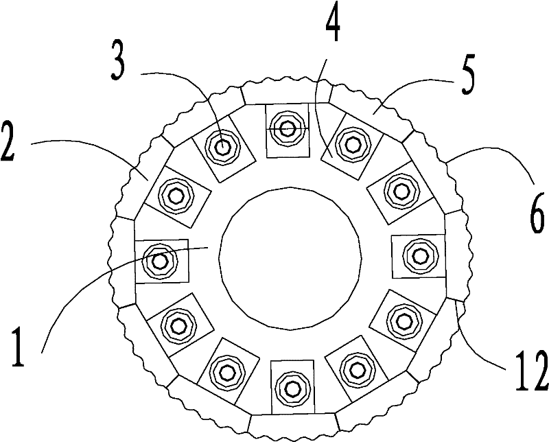
[0066] Such as Figure 1 to Figure 6 As shown, the composite rolling roll includes a roll ring 2 and a core roll 1, the cross section of the core roll 1 is a regular 12-sided shape, and the outer surface of the core roll 1 forms 12 mounting surfaces 7, and the roll ring 2 is composed of Composed of 12 slugs 5, the 12 slugs 5 correspond to the 12 installation surfaces 7 one by one, the bottom surface 10 of each slug 5 fits and contacts with the corresponding installation surface 7 respectively, the bottom surface of each slug 5 There are 3 column pins on the top, and 3 pin holes are provided on the corresponding mounting surface 7, and the above column pins are embedded in the pin holes one by one, and the two ends of each insert 5 are respectively provided with insert legs 4, which correspond to the The two ends of the mounting surface 7 corresponding to the insert block 5 are respectively provided with insert grooves 8 adapted to the above-mentioned insert legs 4, and the abo...

Embodiment 2

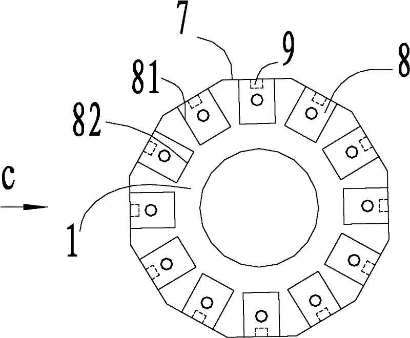
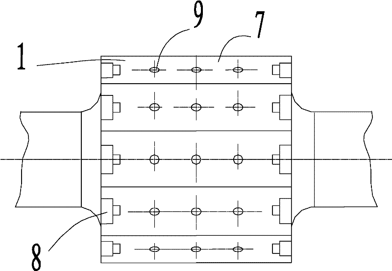
[0068] Such as figure 1 as well as Figure 7 to Figure 12 As shown, the composite rolling roll includes a roll ring 2 and a core roll 1, the cross section of the core roll 1 is a regular 12-sided shape, and the outer surface of the core roll 1 forms 12 mounting surfaces 7, and the roll ring 2 is composed of 12 slugs 5, the 12 slugs 5 correspond to the 12 installation surfaces 7 one by one, the bottom surface 10 of each slug 5 fits and contacts with the corresponding installation surface 7 respectively, and the two slugs of each slug 5 Inlay legs 4 are respectively provided at the ends, and the two ends of the mounting surface 7 corresponding to the inlay block 5 are respectively provided with inlay grooves 8 adapted to the above-mentioned inlay legs 4, and a convex key is arranged on the bottom surface of each inlay block 5, so that The convex key extends from one end of the bottom surface 10 of the inlay block 5 to the other end, and the two ends of the convex key are respec...

Embodiment 3

[0070] The manufacturing method of the slug of compound roll, comprises the following steps:

[0071] A, through the electroslag furnace and the crystallizer one-time forming, form the fusion casting of one-piece structure, wherein, the fusion casting comprises the described inlay block, inlay leg and convex key, and the material composition of the fusion casting comprises by weight percentage:

[0072] C: 0.30-4.00%, Cr: 3.0-7.0%, Ni: 0.5-3.0%, Mo: 0.30-1.0%, W: 0.5-2.0%, V: 0.20-0.80%,

[0073] Ti: 0.10-0.50%, B: 0.001-0.05%, Nb: 0.05-1.50%, N: 0.50-1.50%, and the rest is Fe;

[0074] B. Anneal the molten casting, wherein the annealing process is: put into the furnace at normal temperature, heat up to 650°C with the furnace and keep it for 2.5 to 3 hours, continue to heat up to 920°C and keep it for 4 to 4.5 hours, and slowly cool with the furnace to 600°C The following, out of the oven and air-cooled;

[0075] C, carry out rough machining to the melting and casting that st...


PUM


Abstract

The invention discloses a composite roller and a method for manufacturing an insert of the composite roller. The composite roller can resist large torque and is convenient to mount, detach and maintain. The roller comprises a core roller with an N-side cross section, and a roller ring consisting of N inserts, wherein the N inserts are arranged on N mounting surfaces of the core roller in a one-to-one correspondence mode; the bottom surface of each insert is contacted with a corresponding mounting surface; two ends of each insert are provided with insert legs; two ends of the mounting surface corresponding to each insert are provided with insert grooves matched with the insert legs; and the insert legs are inserted into the insert grooves and are connected with the core roller through bolts. In addition, the bottom surfaces of the inserts and the mounting surfaces are provided with convex parts and groove parts which correspond one to one so as to further improve the torsional behavior of the roller. In the method for manufacturing the insert, the insert, insert legs and a convex key which are integrated are formed at one time by an electroslag furnace and a crystallizer.

Description

technical field [0001] The invention relates to a composite rolling roll with inserts used in mine roller mills and metallurgical rolling mills and a method for manufacturing the inserts of the composite rolling rolls. Background technique [0002] The high-pressure roller mill and its system technology can reduce the power consumption of the grinding system by 20-100%, and increase the output by 25-200%. The grinding system solves technical problems such as drying, low output, and high wear. Its advantages of reducing power consumption, increasing mineral activity, and improving particle composition are becoming the standard supporting process for slag and steel slag micropowder. In the preparation of pellets, the high-pressure roller mill completely replaces the original wet grinding process, increases the specific area of ​​the fine powder, reduces the amount of bentonite, reduces the cost, and improves the quality of the pellets. [0003] At present, the structure of th...

Claims


Application Information

Patent Timeline
Patent Type & Authority Patents(China)
IPC IPC(8): B21B27/02B02C4/30B22D23/10C22C38/54C22C38/56
Inventor 何德武桑曙光
Owner PANZHIHUA LIYU MINING
Why Eureka
Try Eureka