High pressure common rail device with variable high pressure volume for high pressure common rail fuel system

A high-pressure common rail and fuel system technology, applied in fuel injection devices, charging systems, engine components, etc. Affect the fuel injection accuracy of the injector and other problems, achieve the effect of quick start, maintain pressure stability, and eliminate pressure fluctuations

Inactive Publication Date: 2011-10-12
BEIJING UNIV OF TECH
View PDF5 Cites 4 Cited by
  • Summary
  • Abstract
  • Description
  • Claims
  • Application Information

AI Technical Summary

Problems solved by technology

Since the volume of the high-pressure oil rail is not variable, it will lead to the following problems: 1) The volume of the high-pressure oil rail matched with the large circulating oil volume does not meet the requirements of the working conditions under medium and low speeds and medium and small loads
[0005] Since the fuel injectors of each cylinder are connected to the same fuel rail, each fuel injector will cause the fuel pressure in the fuel rail to fluctuate during the fuel injection process, thus affecting the fuel injection accuracy of itself and other fuel injectors
The interior of the high-pressure fuel rail generally adopts a barrel-shaped smooth structure without energy-absorbing elements, so the physical structure of the high-pressure fuel rail cannot realize the vibration absorption and vibration reduction of the high-pressure fuel pressure wave

Method used


Image

  • High pressure common rail device with variable high pressure volume for high pressure common rail fuel system
  • High pressure common rail device with variable high pressure volume for high pressure common rail fuel system
  • High pressure common rail device with variable high pressure volume for high pressure common rail fuel system

Examples


Embodiment Construction

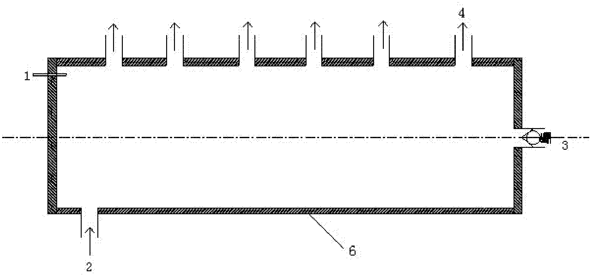
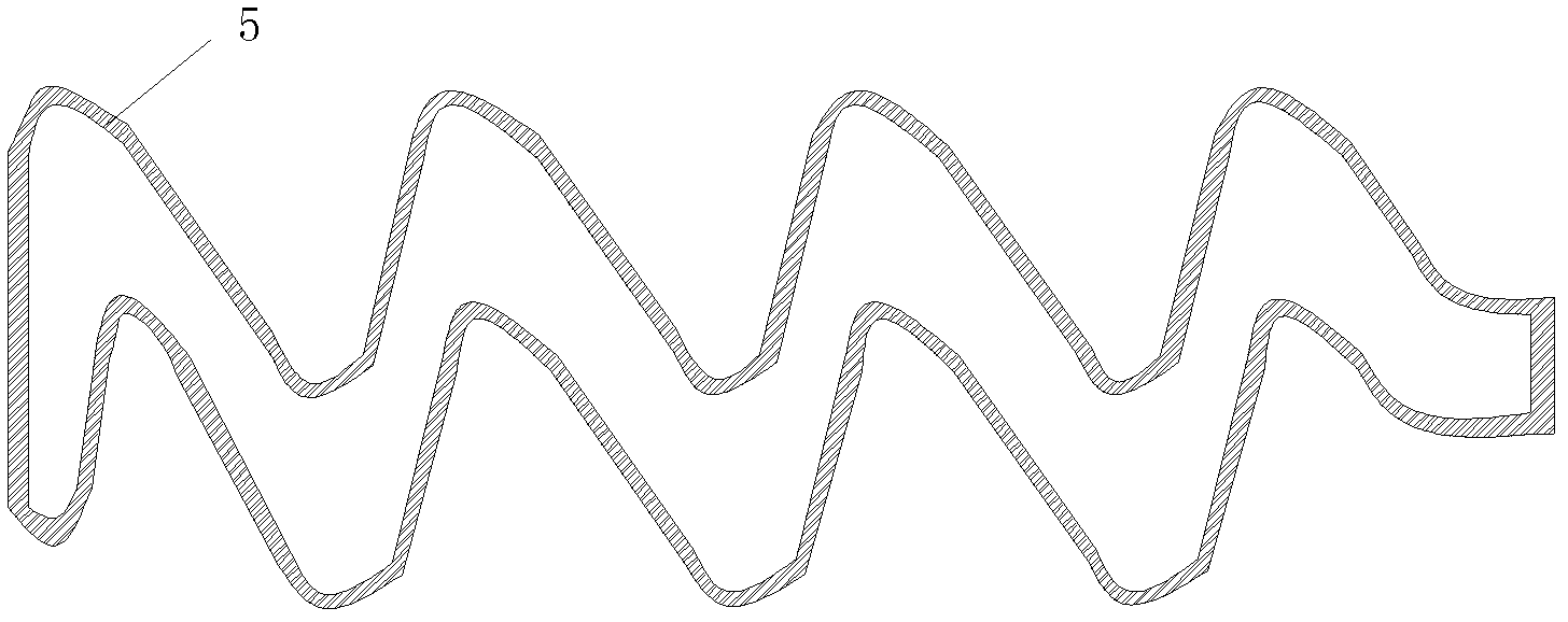
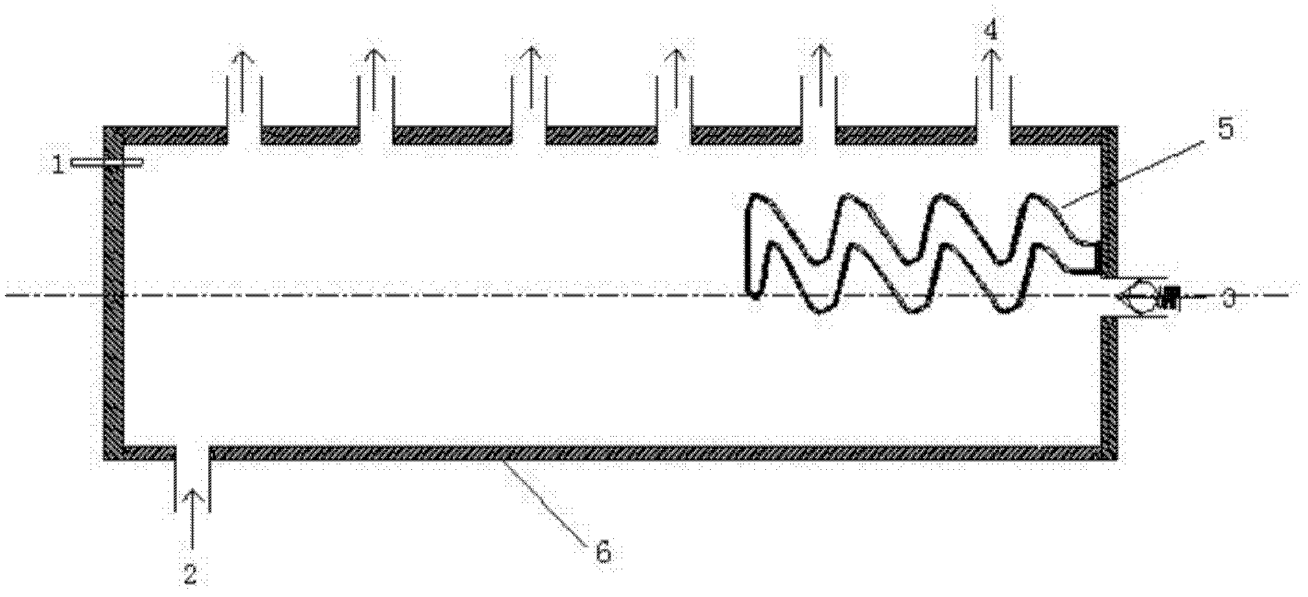
[0015] The specific technical solution of the present invention is that on the basis of the original high-pressure oil rail device of the present invention, an elastic sealing cavity is added in the high-pressure oil rail, and the two are connected by welding. A rail pressure sensor, oil inlet, pressure limiting valve and 6 oil outlets are installed on the high-pressure fuel rail. Fuel flows into the high-pressure fuel rail through the fuel inlet. The electronic control system measures the pressure in the high-pressure fuel rail through the rail pressure sensor. For safety, when the fuel pressure exceeds the limit value, the pressure limiting valve will open, and the fuel will flow out of the high-pressure fuel rail. Fuel can flow out of the fuel injectors injected into each cylinder through the fuel outlet. The structural diagram of the original high-pressure oil rail device is attached figure 1 shown.

[0016] The elastic sealing chamber is made of metal material with a bu...


PUM


Abstract

The invention relates to an elastic high pressure common rail device with variable high pressure volume for an engine high pressure common rail fuel system. The device provided by the invention comprises a high pressure common rail and an elastic seal cavity which is additionally arranged in the high pressure common rail, wherein the cavity is made from a material with the bulk modulus coefficient less than 1500 N / mm<2> and can be easy to compress, the cavity is processed into a saw tooth shape, the cavity is filled with seal fuel oil. On the one hand, when an engine needs the high pressure common rail fuel system to spray systemic circulation oil mass, the pressure of the high pressure fuel oil in the high pressure common rail is greater than the pressure in the elastic seal cavity, the volume of the elastic seal cavity is decreased due to extrusion, and the effective oil supply volume of the corresponding high pressure common rail is increased. On the other hand, when the engine is in a state of medium-low speed and medium-low load, the oil pressure in the high pressure common rail is reduced, the elastic seal cavity expands due to the interior high pressure effect, the effective oil supply volume of the high pressure common rail is decreased, and finally the high pressure common rail inner volume changes along with the oil-rail pressure.

Description

Technical field: [0001] The invention relates to a high-pressure common rail fuel injection system, in particular to a high-pressure common rail oil rail device in the high-pressure common rail fuel injection system. technical background: [0002] Today, with increasingly stringent requirements for energy saving and environmental protection, the high-pressure common rail electronically controlled fuel injection technology, which is known for its flexible control, is an important direction for the development of diesel engine technology. The high-pressure common rail fuel system does not depend on the engine speed to achieve high-pressure injection. During the injection process, the fuel rail pressure remains unchanged, and the fuel injection rate can be adjusted through multiple injections, which can obtain an ideal injection pattern and meet the overall requirements. machine needs. [0003] The high-pressure fuel rail in the high-pressure common rail fuel system is a compo...

Claims


Application Information

Patent Timeline
IPC IPC(8): F02M55/02
Inventor 仇滔尹文辉
Owner BEIJING UNIV OF TECH
Why Eureka
Try Eureka