Thermal environmental control system
A technology for controlling systems and thermal environments, applied in air conditioning systems, refrigerators, household heating, etc., can solve the problems of inability to realize continuous conversion and adjustment of natural cooling, no obvious reduction, high energy consumption of computer room air conditioners, and achieve obvious equipment loss , obvious effect, energy-saving effect and obvious effect of reducing
- Summary
- Abstract
- Description
- Claims
- Application Information
AI Technical Summary
Problems solved by technology
Method used
Image

Examples
Embodiment 1
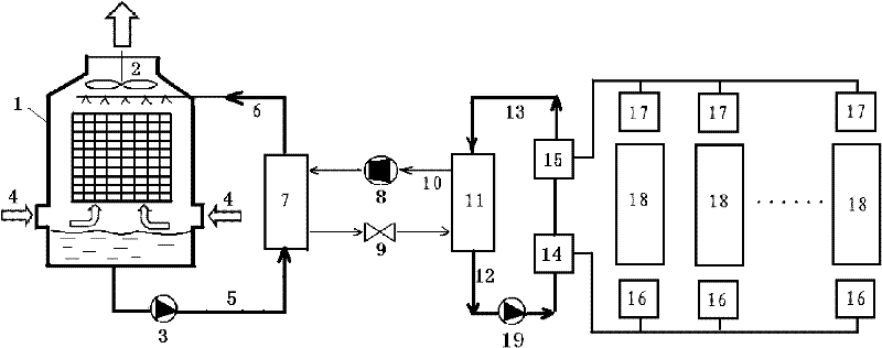
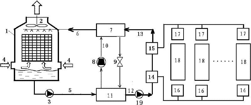
[0020] Such as figure 2 As shown, the difference between the thermal environment control system provided by this embodiment and the air-conditioning system of the prior art is: the inlet of the condenser 7 shell of the refrigerant circulation system is connected to the high-temperature chilled water pipe 13, and the outlet is connected to the cooling tower return pipe 6; The inlet of the shell of the evaporator 11 of the refrigerant circulation system is connected to the outlet pipe 5 of the cooling tower, and the outlet is connected to the low-temperature chilled water pipe 12, thereby forming an open cooling tower series cold water circulation unit.
[0021] During the operation of this embodiment, the compressor 8 of the refrigerant circulation system is usually not started, and the heat emitted by the indoor heat source 18 is sent to the water-heat pipe heat exchanger 14 through the air-heat pipe heat exchanger 16, and the air-heat pipe heat exchanger 14 passes through the...
Embodiment 2
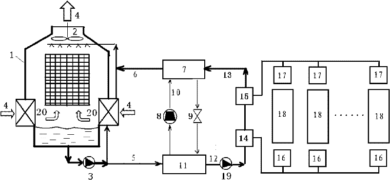
[0023] Such as image 3 As shown, the difference between the thermal environment control system provided by this embodiment and Embodiment 1 is that an air precooling heat exchanger 20 is set at the outdoor air inlet 4 of the cooling tower, and the heat exchange of the air precooling heat exchanger 20 The pipe inlet is connected to the outlet pipe 5 of the cooling tower, and the outlet is connected to the spray pipe at the top of the cooling tower 1.
[0024] When this embodiment works, it is basically the same as Embodiment 1, except that the outdoor air 4 needs to be pre-cooled by the air precooling heat exchanger 20 before entering the cooling tower 1, so that the outlet water temperature of the cooling tower 1 is close to that of the air. dew point temperature. In this way, under the same outdoor working condition, this embodiment can further reduce the load borne by the compressor 8 and further reduce the cooling power consumption of the compressor 8 .
Embodiment 3
[0026] Such as Figure 4 As shown, the difference between the thermal environment control system provided by this embodiment and Embodiment 1 is that: the cooling tower 1 is provided with heat exchange coils 21 that are spirally coiled or rotated in rows, and the heat exchange coils 21 The inlet is connected to the return pipe 6 of the cooling tower, and the outlet is connected to the outlet pipe 5 of the cooling tower, thereby forming a closed cooling tower series cold water circulation unit. At the same time, a spray water supply pipe 22 and a water pump 23 are drawn from the bottom of the cooling tower 1 to supply water to the spray pipe at the top of the cooling tower 1 .
[0027] When this embodiment works, it is basically the same as Embodiment 1. The difference is that the circulating cold water enters the cooling tower 1 through the coil 21, and then exchanges heat with the air and spray water in the spray tower 1, which can effectively Unfavorable conditions such as ...
PUM
 Abstract
Description
Claims
Application Information
 - R&D
- Intellectual Property
- Life Sciences
- Materials
- Tech Scout
- Unparalleled Data Quality
- Higher Quality Content
- 60% Fewer Hallucinations
Browse by: Latest US Patents, China's latest patents, Technical Efficacy Thesaurus, Application Domain, Technology Topic, Popular Technical Reports.
© 2025 PatSnap. All rights reserved.Legal|Privacy policy|Modern Slavery Act Transparency Statement|Sitemap|About US| Contact US: help@patsnap.com