Method for producing laminate, and laminate

A technology of a laminate and a manufacturing method, which is applied in the manufacture of printed circuit precursors, printed circuit manufacturing, lamination, etc., can solve the problems of air and foreign matter mixing, increase in peel strength, and bellows effect, etc. The effect of easy peeling and improved productivity

Active Publication Date: 2011-10-12
JX NIPPON MINING & METALS CORP
View PDF12 Cites 4 Cited by
  • Summary
  • Abstract
  • Description
  • Claims
  • Application Information

AI Technical Summary

Problems solved by technology

That is, there is a problem of producing a bellows effect
[0021] In addition, the following Patent Document 9 proposes a copper foil with a carrier with a structure bonded over the entire surface, but in this case, the peeling strength increases, making it difficult to perform the peeling operation, and bending occurs during handling. Under the influence of this bending, there is a problem that air and foreign matter are mixed into the weakly bonded part

Method used


Image

  • Method for producing laminate, and laminate
  • Method for producing laminate, and laminate
  • Method for producing laminate, and laminate

Examples


Embodiment 1

[0140] A 40 μm aluminum foil was used for the carrier A, and a 35 μm copper foil was used as a foil to be bonded thereto. Using an adhesive with a viscosity of 2 million to 3 million mPa·s, the carrier A was unwound from the bobbin and coated with a width of 3 mm on opposite ends. Apply in a linear form.

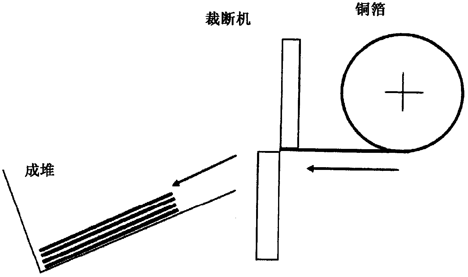
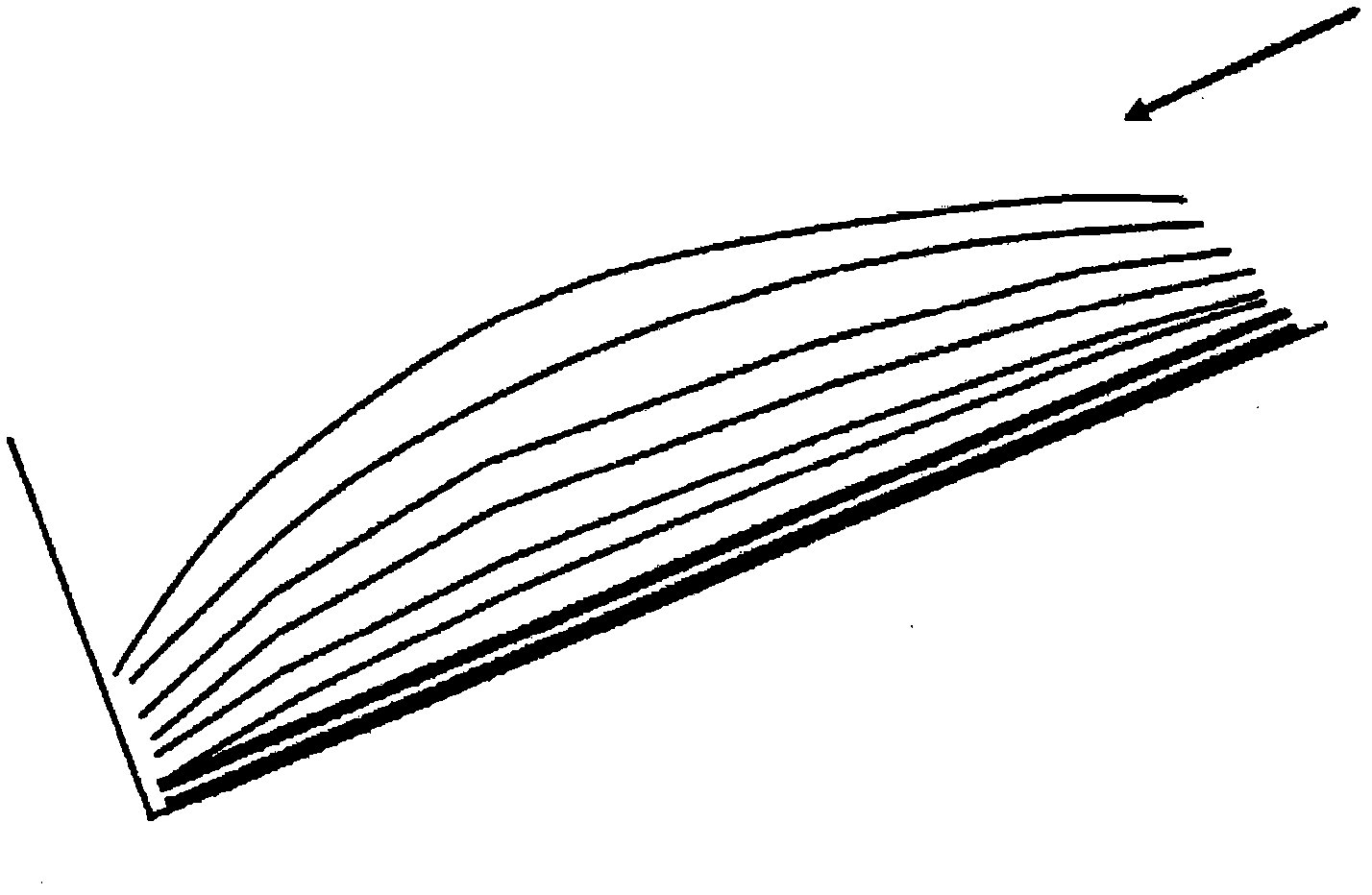
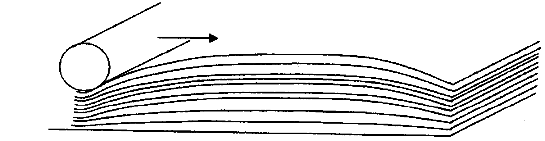
[0141] On the side where the adhesive is applied, metal foil B is stacked while being unwound from the bobbin, the two are bonded, and then cut, and the cut laminates are piled up, starting from the upper part of the cut product. Add rollers (air removal).

[0142] As a result, if the viscosity is 2 million to 3 million mPa·s, it can be pasted without causing wrinkles or cracks.

[0143] In addition, when the viscosity was 5 million mPa·s, wrinkles occurred, and problems occurred in the laminated body.

Embodiment 2

[0145] A 12 μm aluminum foil was used for the carrier A, and a 9 μm copper foil was used as a foil to be bonded thereto. Use an adhesive with a viscosity of 800,000-900,000 mPa·s, and the coating width is 3 mm. Apply in a linear form. The procedure for bonding to the adding roll was the same as in Example 1.

[0146] Since the carrier or copper foil is thin, if the viscosity is lower than that of Example 1, that is, 800,000 to 900,000 mPa·s, some waviness will be observed, but it can be pasted without wrinkles or cracks.

[0147] On the other hand, when the viscosity was 2,000,000 mPa·s, wrinkling occurred and a problem occurred in the laminated body.

[0148] It can be seen from this that the viscosity of the applied adhesive needs to be adjusted according to the material and thickness of the carrier A used.

Embodiment 3

[0150] A copper foil of 18 μm was used for the carrier A, and a copper foil of 5 μm was used as a foil to be bonded thereto. Apply the adhesive in a 3 mm wide line. The process of sticking to the adding roll is the same as in Example 1.

[0151] In this case, since the copper foil is thinner than that of Example 2, if the viscosity is 8000-10000 mPa·s, some waviness is observed, but it can be pasted without causing wrinkles or cracks.

[0152] On the other hand, when the viscosity is 1,500,000 mPa·s, wrinkles and cracks are generated, and a problem occurs in the laminated body.

[0153] It can be seen from this that the viscosity of the applied adhesive needs to be adjusted according to the material and thickness of the carrier A used.


PUM

PropertyMeasurementUnit
viscosityaaaaaaaaaa
viscosityaaaaaaaaaa
thicknessaaaaaaaaaa

Abstract

The disclosed method comprises applying an adhesive onto both of the opposing edge portions of a carrier (A) being fed by winding-off from a bobbin, adhering a metal foil (B) continuously wound off from a second bobbin to the adhesive-applied side of the face of the carrier in lamination, cutting this laminate into sheets, and stacking orderly the cut laminate sheets; and when the cut and stacked laminate sheets constituted of the orderly stacked laminates comes to rise remarkably at the middle portion thereof, the stack of laminates is roll-pressed on the upper face of the cut and stacked laminate sheets to remove the air from the spaces between the cut laminate sheets and inside of the laminates, and then, curing the adhesive to allow the laminated sheets to adhere together. In particular, the disclosed method is characterized by the carrier-supported copper foil employed in the production of laminate plates, and intends cost reduction in a print substrate production process by improvement of handling property and the production yield.

Description

technical field [0001] The present invention relates to a method for producing a laminate composed of a copper foil with a carrier used in the manufacture of a single-sided or two or more-layer multilayer laminate used in a printed wiring board, and to a laminate. Background technique [0002] A representative example of a multilayer laminate is a printed circuit board. In general, the basic composition of printed circuit boards is dielectric materials, which are obtained by impregnating synthetic resins in substrates such as synthetic resin plates, glass plates, glass non-woven fabrics, and paper, and are called "prepregs". ". [0003] Conductive copper or copper alloy foil or the like is bonded to the prepreg surfaces (front and back). The laminate assembled in this way is generally called a CCL (Copper Clad Laminate: Copper Clad Laminate) material. Furthermore, the structure in which the copper foil is multilayered by passing the prepreg over the CCL material is called...

Claims


Application Information

Patent Timeline
Patent Type & Authority Applications(China)
IPC IPC(8): B32B37/00B32B15/04H05K3/00
CPCB32B37/0007B32B37/0076B32B37/1292B32B38/0004B32B2307/54B32B2309/105B32B2311/12B32B2457/08B65H2301/4223B65H2601/211H05K3/025H05K2203/0143H05K2203/0228H05K2203/068H05K2203/1178B32B37/003B32B15/00B32B37/12Y10T156/1052Y10T428/24826Y10T428/24917B32B37/20B32B38/0012B32B37/1284H05K3/00H05K3/4611
Inventor 高森雅之
Owner JX NIPPON MINING & METALS CORP
Why Eureka
Try Eureka