Rocket and antiaircraft gun operation control and safety monitoring system and operation monitoring method
A security monitoring system, ignition controller technology, applied in the direction of the gun control system, weapon accessories, offensive equipment, etc., can solve the problem of inability to automatically collect operation information and upload operation information in real time, artificial weather modification operations cannot be unified management, Uncontrolled weather operations and other issues, to achieve the effect of simple installation, easy maintenance, and high degree of modularization
- Summary
- Abstract
- Description
- Claims
- Application Information
AI Technical Summary
Problems solved by technology
Method used
Image

Examples
Embodiment 1
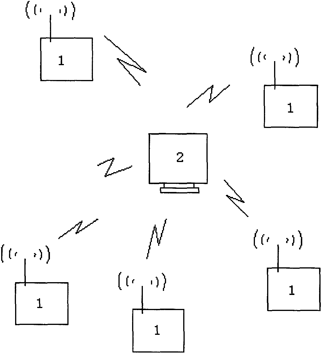
[0032] This embodiment provides a rocket operation control and safety monitoring system and an operation monitoring method. refer to figure 1 , the rocket operation control and safety monitoring system in this embodiment includes a plurality of operation point acquisition control units 1 and a weather modification operation center management platform, namely the upper computer 2; the upper computer 2 and the operation point acquisition control unit 1 Data transmission between mobile communication GPRS;
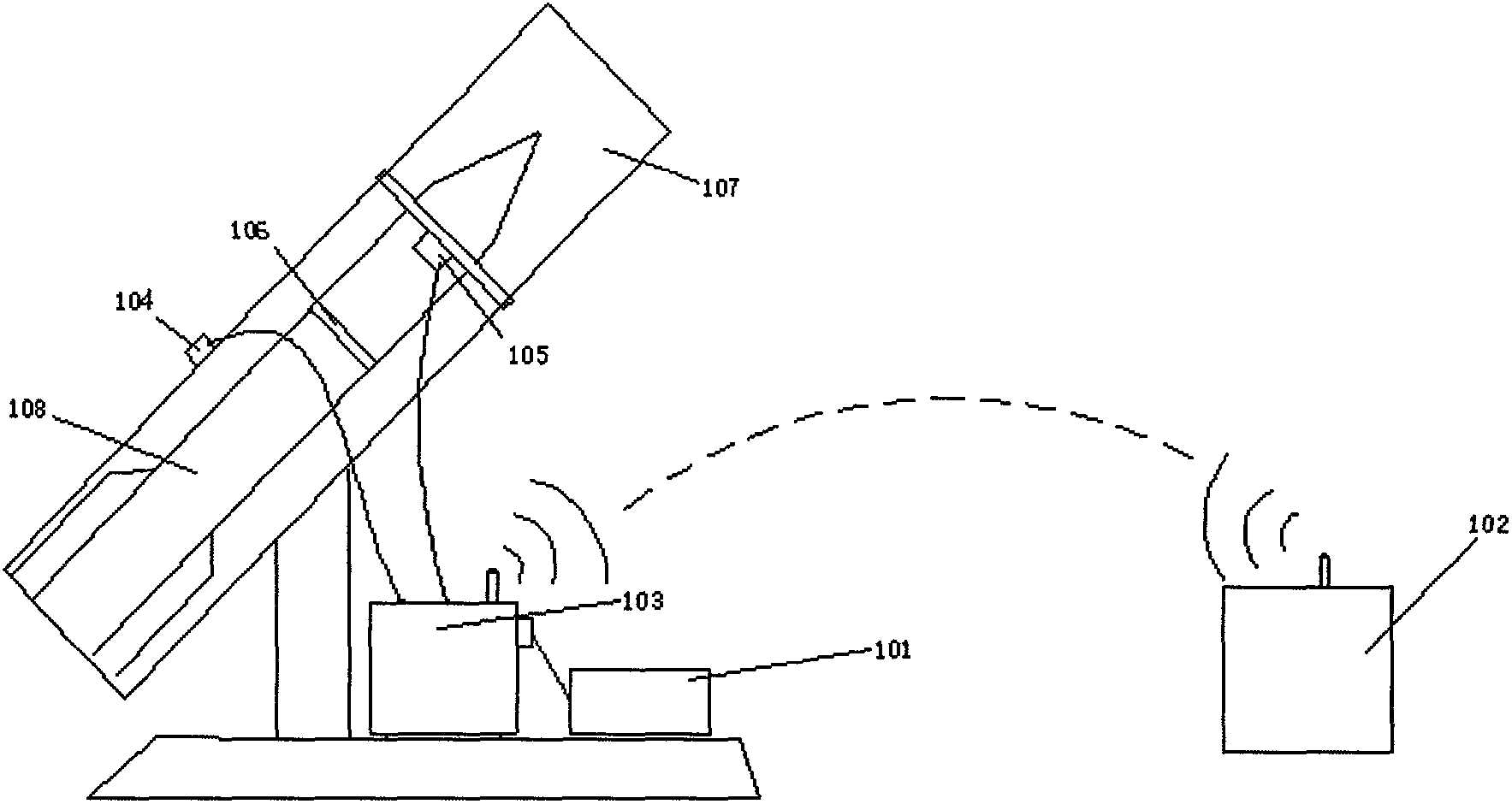
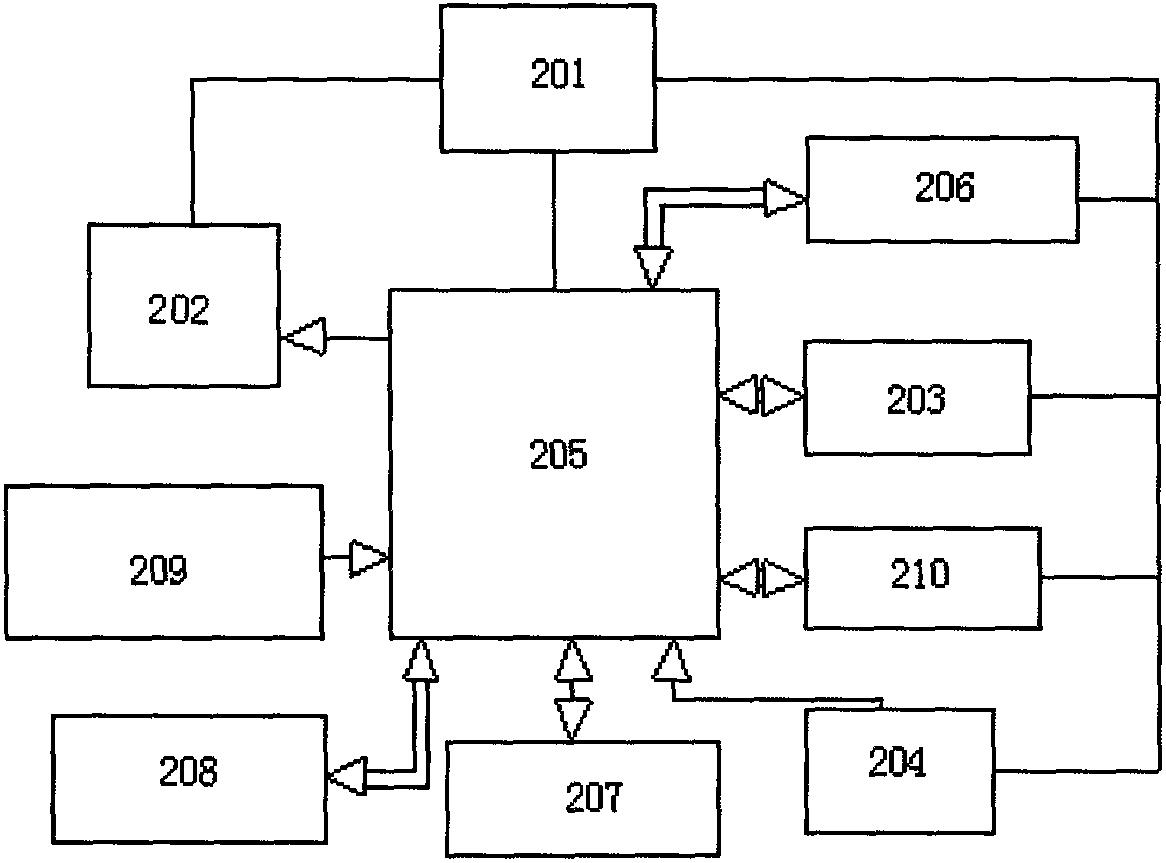
[0033] refer to figure 2 , wherein one operating point acquisition control unit 1 is composed of an ignition controller 101, an information relay controller 102, a collector 103, a pitch and azimuth angle reader 104, a rocket or shell identification device 105, an electronic identity tag 106, a launcher, The rocket is composed; the rocket is installed on the launcher; the electronic identity tag 106 is installed on the rocket, the pitch and azimuth reader 104, and the rocke...
Embodiment 2
[0052] This embodiment provides an antiaircraft artillery operation control and safety monitoring system and operation monitoring method. refer to figure 1 , the antiaircraft gun operation control and safety monitoring system in this embodiment includes a plurality of operating point acquisition control units 1 and a host computer 2; the upper computer 2 and the operating point acquisition control unit 1 communicate through 3G;
[0053] refer to figure 2, one of the operating point acquisition control unit 1 is composed of an ignition controller 101, an information transfer controller 102, a collector 103, a pitch and azimuth reader 104, a shell identification device, an electronic identity tag 106, an antiaircraft gun, and a shell; The shell is installed on the anti-aircraft gun; the electronic identity tag 106 is fixed on the shell, and the pitch, azimuth reader 104 and the shell ID identifier are fixed on the anti-aircraft gun; the collector 103 reads the pitch , the inf...
PUM
 Abstract
Description
Claims
Application Information