High power fin cold plate radiator and manufacturing method thereof

A manufacturing method and technology of finned cold plates, which are applied in semiconductor/solid-state device manufacturing, electrical solid-state devices, semiconductor devices, etc., can solve problems such as high cost, low heat dissipation efficiency, and failure to achieve high-fold finning, and achieve small deformation and improved The effect of the heat transfer effect

Inactive Publication Date: 2011-11-02
苏州三川换热器股份有限公司
View PDF3 Cites 17 Cited by
  • Summary
  • Abstract
  • Description
  • Claims
  • Application Information

AI Technical Summary

Problems solved by technology

[0004] The brazed cold plate radiator first produces the base plate and heat sink, and then welds the heat sink and base plate through overall vacuum brazing. Vacuum welding consumes a lot of energy and costs high
[0005] The aluminum profile one-piece extruded cold plate radiator is formed by one-piece extrusion of aluminum alloy. Its advantage is that the structure is simple, but the thickness of the heat sink cannot be made thin (generally at least 0.8mm), and the height of the heat sink cannot be made high. The spacing of the fins cannot be made small (generally at least 3mm), that is, it is impossible to achieve high finning (finning: the ratio of fin height to fin spacing), which makes the amount of metal required per unit heat dissipation area large and the heat dissipation efficiency is low.
[0006] The shovel-fin cold plate radiator uses a knife to shovel out the heat sink on the heat dissipation surface of the substrate. The disadvantage is that the thickness of the heat sink is thick (generally at least 3mm), the height of the heat sink cannot be made high, and the distance between the heat sinks Larger (generally up to 10mm), even less able to meet the requirements of high-power wings

Method used


Image

  • High power fin cold plate radiator and manufacturing method thereof
  • High power fin cold plate radiator and manufacturing method thereof
  • High power fin cold plate radiator and manufacturing method thereof

Examples


Embodiment

[0038]Example: see attached figure 1 ~As shown in attached drawing 6:

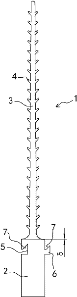
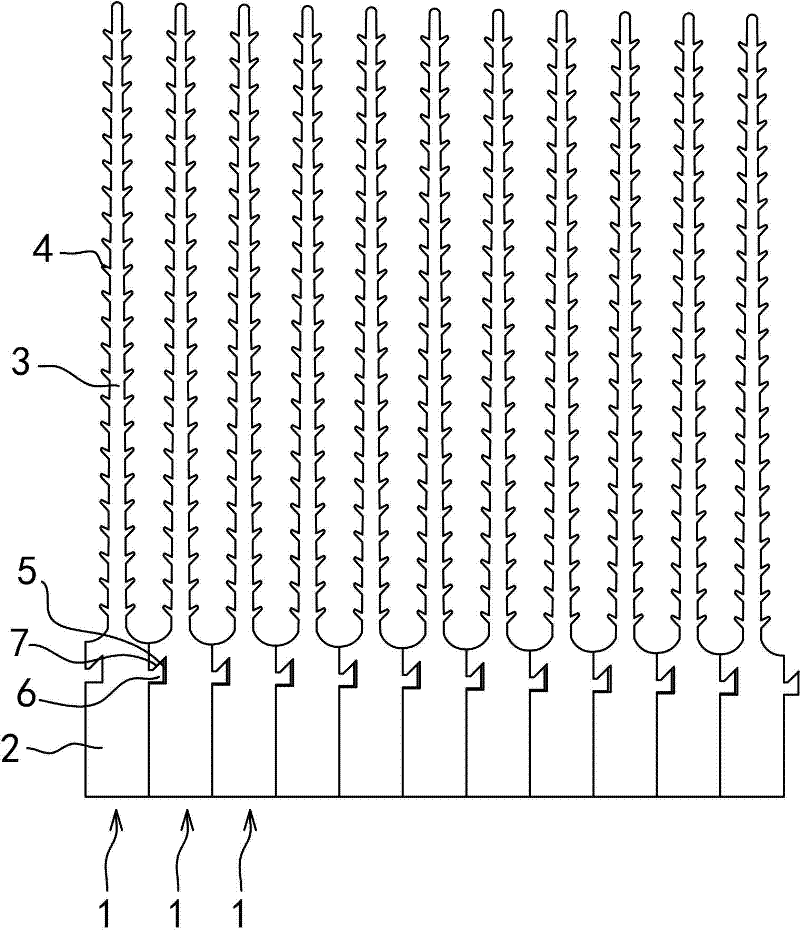
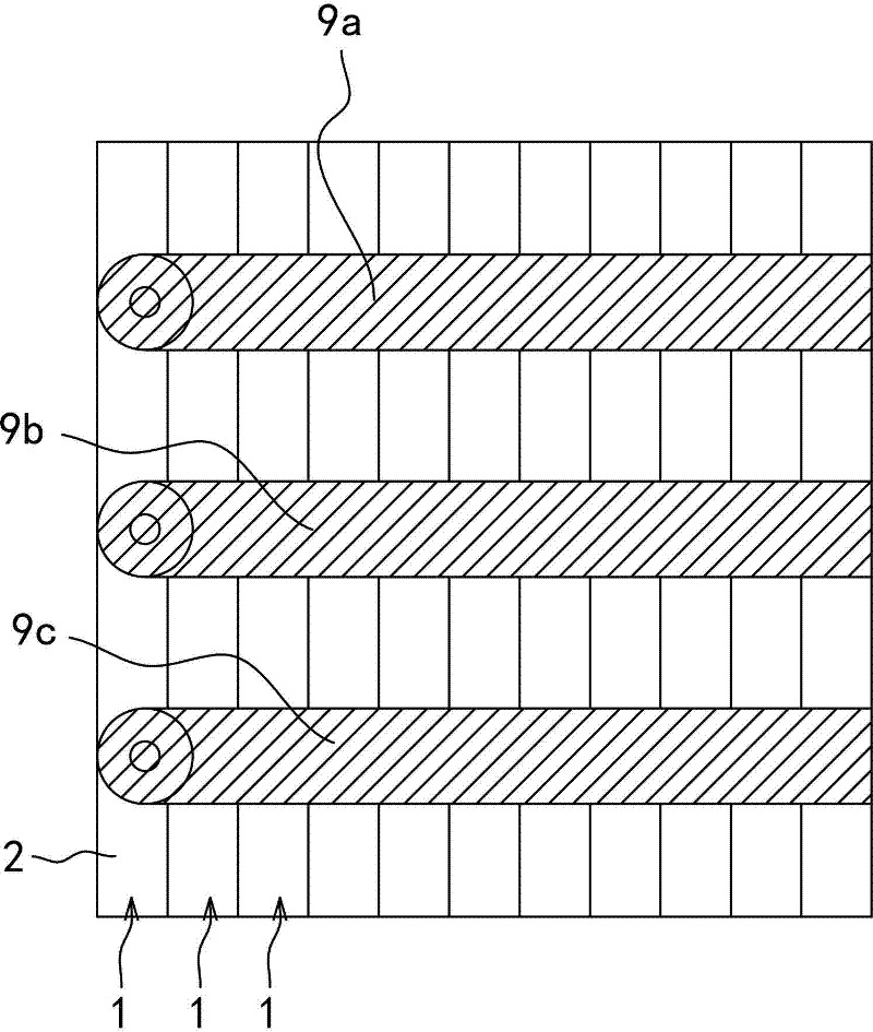
[0039] The utility model relates to a high-power-finned cold-plate radiator, which is composed of a plurality of heat-dissipating units 1 assembled together.

[0040] As shown in the accompanying drawing 1, each heat dissipation unit 1 is an extruded aluminum or copper profile with equal cross-section, and the cross-sectional profile is composed of a base plate 2 and a fin portion 3 protruding upward from the base plate 2 . The cross-sectional shape of the substrate portion 2 is rectangular, while the cross-sectional shape of the fin portion 3 is a vertical strip. Specific as figure 1 As shown, the width of the cross-section of the fin part 3 gradually narrows upward from the root, and a plurality of protruding strip-shaped thorns 4 are provided on both sides of the fin part 3 to increase the surface area. Moreover, among the opposite sides in the width direction of the base plate part 2 of each cooling...


PUM


Abstract

The invention relates to a high power fin cold plate radiator and a manufacturing method thereof. Provided is a high power fin cold plate radiator. The radiator is characterized in that it is formed by merging a plurality of radiation cells; the radiation cells are aluminium or copper extrusion moulding uniform cross section bars; the radiation cells are arranged in the width direction; the substrate portion of each adjacent radiation cells uses a stripe-shaped hook to plug with a corresponding slot and the stripe-shaped hook and the slot abut against each to cooperate with an upward or downward inclined plane; when one of the two adjacent radiation cells is impacted with an active force in an up and down direction, the stripe-shaped hook and the slot oppositely slide along the inclined plane to make the adjacent radiation cells become closer so that a clamp structure among the radiation cells is formed and the substrate portions are welded together with a stirring friction welder. The invention is characterized by simple manufacture. The height of the fin can be increased, the thickness of the fin can be reduced, the spacing between the fins after the radiation cells are merged together can be reduced to achieve the requirement of high power fins and 25-time to 40-time fins can be manufactured.

Description

technical field [0001] The invention relates to a radiator, in particular to a cold plate radiator. Background technique [0002] Radiators are often used for heat dissipation and cooling of power components. There are many power components in the products of the electronic power industry. During use, 5% to 8% of the power loss generates heat, which makes the temperature of the components rise and the working state deteriorates. Reliable The reliability is greatly reduced until it is damaged. In a certain temperature range, the temperature of the power element increases by 5°C, and the reliability drops by an order of magnitude. Therefore, the performance of the radiator directly affects the reliability of the product. [0003] In the prior art, the structure of the cold plate radiator is generally composed of a base plate and heat sinks fixedly arranged on the heat dissipation surface of the base plate. From the perspective of production methods, it can be divided into bra...

Claims


Application Information

Patent Timeline
Patent Type & Authority Applications(China)
IPC IPC(8): H01L23/367H01L21/48
Inventor 李建明陆国明朱鸣陆姚宏明单俊
Owner 苏州三川换热器股份有限公司
Why Eureka
Try Eureka