
Optical antenna for multipoint laser communication

An optical antenna, multi-point laser technology, applied in optics, optical components, electromagnetic wave transmission systems, etc., can solve the problems of low energy utilization, large receiving aperture, lack of applicability and implementation, and achieve high energy utilization. , the effect of reducing the diameter

Inactive Publication Date: 2011-11-02
CHANGCHUN UNIV OF SCI & TECH
View PDF4 Cites 18 Cited by
  • Summary
  • Abstract
  • Description
  • Claims
  • Application Information

AI Technical Summary

Problems solved by technology

These preliminary ideas about the construction of a specific system for laser communication networking cannot be applied to large-scale space laser communication networking between multiple satellites, and there are technical bottlenecks, which do not have wide applicability and implementation
There is also a Chinese patent "a point-to-multipoint laser communication device based on a multi-component rotating paraboloid structure" (patent application number: 201010199217.1), which uses a rotating paraboloid as an optical antenna. This structure has low energy efficiency and large receiving aperture. , it is very difficult to achieve subsequent optical system processing and arrangement

Method used


Image

  • Optical antenna for multipoint laser communication
  • Optical antenna for multipoint laser communication

Examples


Embodiment Construction

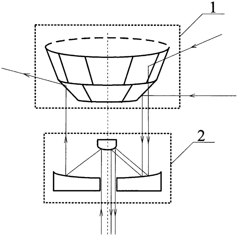
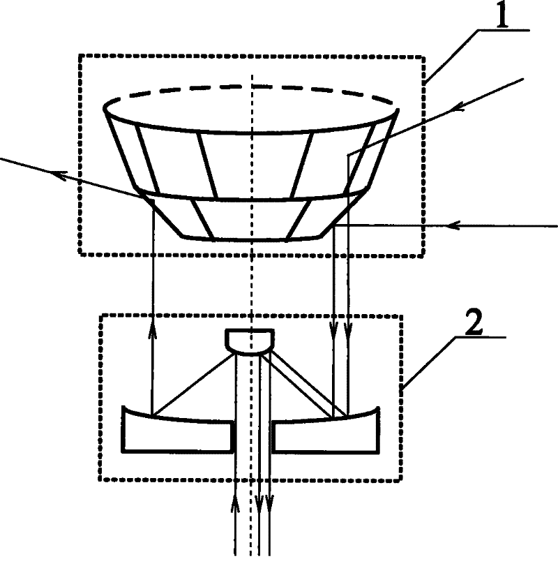
[0012] An optical antenna for multi-point laser communication. Such as figure 1 As shown, it is characterized in that the optical antenna is composed of a multi-mirror splicing optical antenna 1 with an APT control system and a card-type beam reduction system 2 .

[0013] The multi-mirror splicing optical antenna 1 is constructed by improving the surface structure of the paraboloid of revolution. Its construction principle is based on the fact that when the incident light hits the focus of the paraboloid of revolution, the reflected light is a ray parallel to the axis of rotation of the paraboloid of revolution. This feature; the specific construction method is to divide the continuous paraboloid of revolution into M layers along the main axis direction, and the M is a positive integer; for i from 1 to M, construct Ni planes around the axis of rotation of the paraboloid of revolution in the i-th layer Reflectors, each plane reflector is a tangent plane of a paraboloid of revo...


PUM


Abstract

The invention provides an optical antenna for multipoint laser communication and belongs to the technical field of a space laser communication. The optical antenna for multipoint laser communication provided by the invention comprises a multi-reflector splicing optical antenna with an APT (Automatically Programmed Tool) control system and a cassette beam contraction system. The optical antenna provided by the invention is constructed by improving the surface structure of a rotating paraboloid, and the laser communication of one point to multiple points at the whole periphery of the horizontal direction and in the design field angle of the pitching direction can be realized. Because the reflection is carried out by adopting laser beams received by a large-area plane reflector which is formed after multiple small-area plane reflectors are deflected, the optical antenna provided by the invention has higher energy utilization rate compared with the optical antenna with a continuous paraboloid; and simultaneously, the cassette beam contraction system is adopted to compress the diameter of the light beams which are received by a large-caliber optical antenna, thereby reducing the caliber of a subsequent system, reducing the manufacturing design difficulty and being beneficial to the miniaturization of an optical system.

Description

technical field [0001] The invention relates to an optical antenna for multi-point laser communication, which belongs to the technical field of space laser communication. Background technique [0002] In recent decades, many countries in the world have invested a lot of money and manpower in the research of space laser communication technology. achieved a number of results. However, the successful on-orbit laser communication demonstration and verification is still a point-to-point working mode. Domestic and foreign reports mainly focus on the network layer theory and simulation research of space laser communication networking technology, and there are few studies on specific optical antennas. One method is to develop a multi-point receiving scheme using a catadioptric optical system as a receiving antenna (US Patent No.: 6445496 B1); another method is to use a detector array coupled with a focal plane to expand the receiving field of view (US Patent No.: 6912360 B1 ). Th...

Claims


Application Information

Patent Timeline
IPC IPC(8): H04B10/10G02B5/10G02B27/10H04B10/116H04B10/556
Inventor 姜会林胡源赵义武丁莹董科研宋延嵩
Owner CHANGCHUN UNIV OF SCI & TECH
Learn More