Purification equipment and treatment process for tail gas from acrylonitrile absorption tower

A technology of purification equipment and absorption tower, which is applied in the direction of chemical instruments and methods, separation of dispersed particles, separation methods, etc., can solve problems such as increased emissions, and achieve the best effect of reducing emissions and reducing N2O

Inactive Publication Date: 2011-11-09
SHANGHAI NORMAL UNIVERSITY
View PDF1 Cites 18 Cited by
  • Summary
  • Abstract
  • Description
  • Claims
  • Application Information

AI Technical Summary

Problems solved by technology

However, low-temperature combustion technology also leads to N 2 O emissions increase

Method used


Image

  • Purification equipment and treatment process for tail gas from acrylonitrile absorption tower
  • Purification equipment and treatment process for tail gas from acrylonitrile absorption tower
  • Purification equipment and treatment process for tail gas from acrylonitrile absorption tower

Examples


Embodiment 1

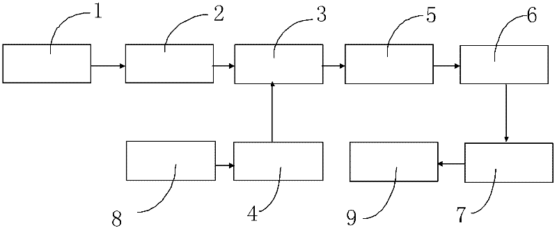
[0033] After the tail gas from the absorption tower passes through the gas-liquid separator 1, it is first preheated by the gas / gas heat exchanger 2, and the temperature rises to 180°C. During the process of flowing to the catalytic reactor 3, fresh air is supplemented by the oxygen supplement fan 4 (Insufficient oxygen content in the original tail gas), the inlet temperature is lowered to 150°C and enters the catalytic reactor 3 for catalytic oxidation reaction, VOCs and CO react with oxygen to generate NOx, H 2 O and CO 2 . Install an external heat exchanger 2 in the middle of the reactor to reduce the temperature of the tail gas and the bed layer, so as to prevent the catalyst from being too high to sinter and deactivate and reduce NO X generation. In the actual process, for the convenience of operation and control, the catalytic reactor is divided into two sections, and the intermediate heat exchanger removes the reaction heat from the front-stage reactor to reduce the o...

Embodiment 2

[0035] The equipment and process are the same as in Example 1, the inlet temperature of the catalytic reactor is about 160°C, the outlet temperature of the catalytic reactor is about 200°C, the removal efficiency of carbon monoxide in the treated exhaust gas reaches 99.7%, and the removal efficiency of non-methane total hydrocarbons reaches 98.2%. After testing, the contents of harmful volatile organic compounds such as carbon monoxide, nitrogen oxides and non-methane total hydrocarbons in the purified tail gas are shown in Table 2.

Embodiment 3

[0037] The equipment and process are the same as in Example 1. The inlet temperature of the catalytic reactor is about 170°C, and the outlet temperature of the catalytic reactor is about 180°C. The removal efficiency of carbon monoxide in the treated exhaust gas reaches 99.6%, and the removal efficiency of non-methane total hydrocarbons reaches 98.0%. After testing, the contents of harmful volatile organic compounds such as carbon monoxide, nitrogen oxides and non-methane total hydrocarbons in the purified tail gas are shown in Table 2.


PUM


Abstract

The invention discloses purification equipment for tail gas from an acrylonitrile absorption tower. The purification equipment comprises a gas-liquid separator for separating the tail gas from the acrylonitrile absorption tower, an air filter for mixing fresh air and the tail gas, an oxygen supply fan and a heat exchanger for heat exchange of mixed gas of the tail gas and the air; the heat exchanger is circularly communicated with a catalytic reactor, and the mixed gas produced after catalytic oxidation reaction is introduced from the top of a denitration reactor through the heat exchanger; the bottom of the denitration reactor is communicated with a waste heat boiler for recycling heat; and a chimney for exhausting the purified tail gas is arranged at the exhaust port of the waste heat boiler. Through the technical scheme, the purification equipment has the following advantages that: by taking the measures of combining a catalytic oxidation system and a selective catalytic reduction denitration system, adopting segmental heat receiving in the catalytic oxidation reactor, reducing redundant oxygen quantity or adopting segmental combustion, operational stability and safety are ensured, and the organic substances and the nitrogen oxides in the treated tail gas accord with the national discharge standards.

Description

technical field [0001] The invention relates to a purification equipment and treatment process for tail gas of an acrylonitrile absorption tower, in particular to a purification treatment method for acrylonitrile tail gas, an important chemical raw material involved in the production of fibers, rubber and plastics in the petrochemical field. Background technique [0002] The main tail gas in the production process of acrylonitrile is the tail gas discharged from the absorption tower, which contains not only propylene, propane and carbon monoxide, but also a small amount of harmful components such as acrylonitrile. At present, some domestic enterprises are still in the state of natural discharge; causing certain pollution to the environment. With the enhancement of people's awareness of environmental protection and the increasingly stringent environmental regulations, the treatment of acrylonitrile tail gas has become an unavoidable challenge for production enterprises. [0...

Claims


Application Information

Patent Timeline
Patent Type & Authority Applications(China)
IPC IPC(8): B01D53/75B01D53/86B01D53/56B01D53/62B01D53/72
Inventor 郭亚军李平朗万中郭亚平王海瑾
Owner SHANGHAI NORMAL UNIVERSITY
Why Eureka
Try Eureka