
Self-gas supply mixed fly ash multistage flotation separation system

A hybrid, fly ash technology, used in flotation, solid separation, etc., can solve the problems of unsatisfactory flotation effect and increased manufacturing cost.

Inactive Publication Date: 2011-11-16
FUJIAN LONGYAN LONGNENG FRYASH COMPREHENSIVE UTILIZATION
View PDF9 Cites 18 Cited by
  • Summary
  • Abstract
  • Description
  • Claims
  • Application Information

AI Technical Summary

Problems solved by technology

[0008] The disadvantages of the above technical solution are: 1. It is necessary to install a separate air injection device in the flotation separation device, which increases the manufacturing cost; 2. The swirling device is used to make the bubbles move upward in a swirling state, and the flotation effect is not ideal

Method used


Image

  • Self-gas supply mixed fly ash multistage flotation separation system
  • Self-gas supply mixed fly ash multistage flotation separation system
  • Self-gas supply mixed fly ash multistage flotation separation system

Examples


Embodiment 1

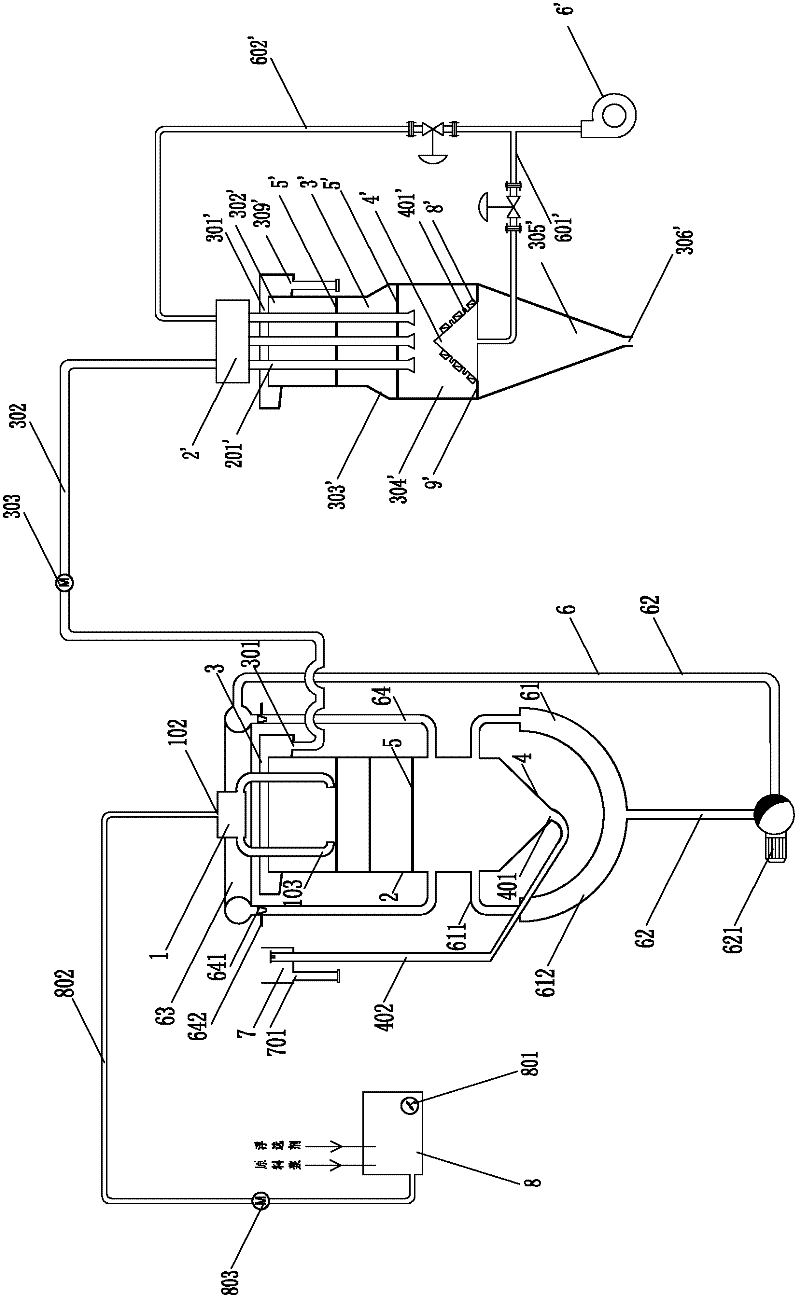
[0052] Such as figure 1 As shown, Example 1 of the present invention includes two flotation separation devices.

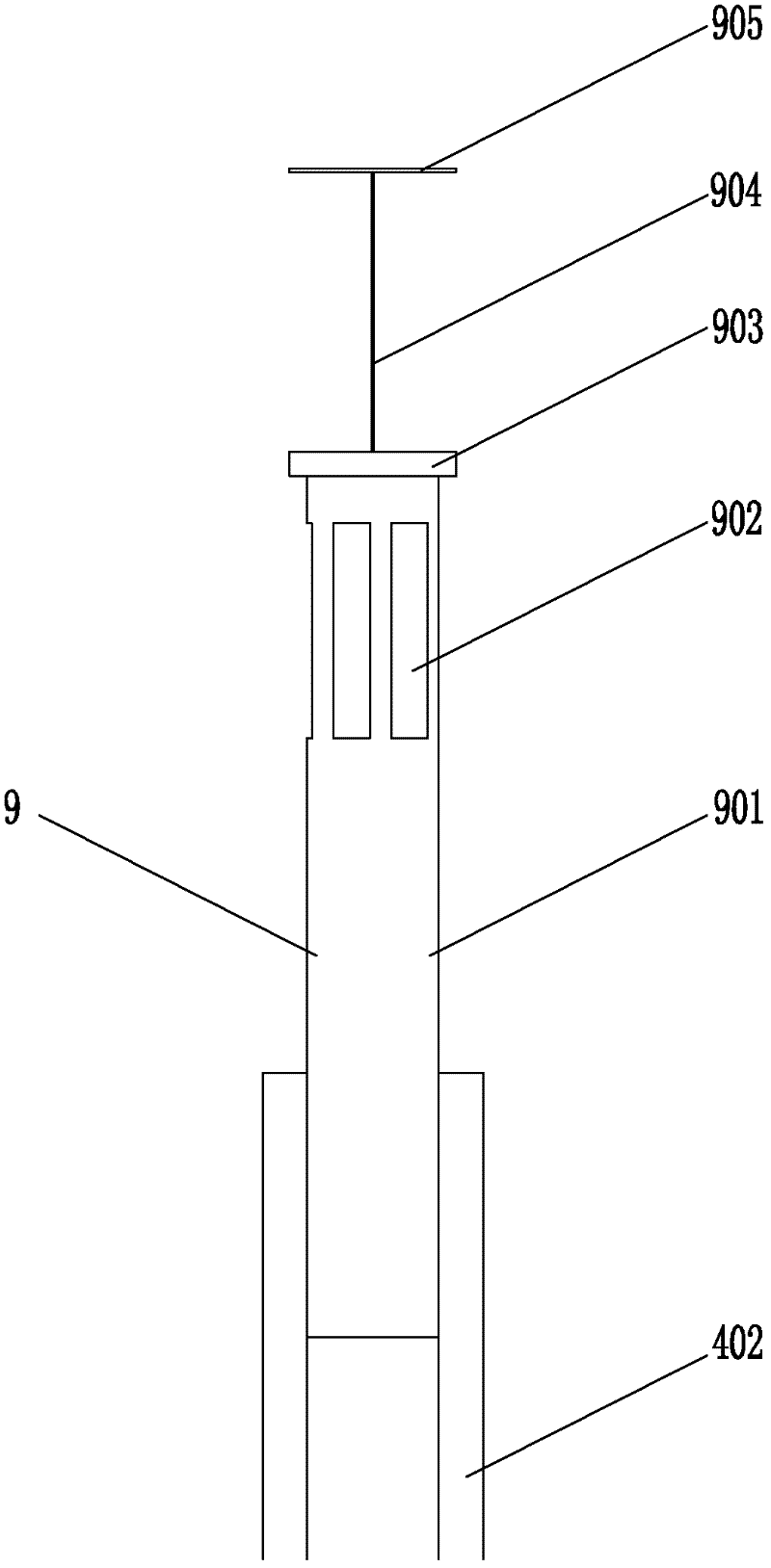
[0053] Wherein, the first flotation separation device is a self-supply type flotation separation device, which includes: a storage device 8, a distribution device 1, a vertical cylinder 2, an overflow collection section 3, a tail ash collection section 4, Multi-layer flotation plate 5, circulation device 6, tail ash box 7, liquid level adjustment device 9.

[0054] Wherein, the material storage device 8 is provided with a stirring device 801 for fully stirring the fly ash raw material slurry and the flotation agent. The lower part of the material storage device 8 is provided with a feeding pipeline 802 on which a slurry pump 803 is arranged, and the feeding pipeline 802 leads to the distribution device 1 .

[0055] The cylinder body 2 is provided with multiple layers of flotation plates 5 (for example, 3 layers) arranged at intervals.

[0056] The overflow colle...

Embodiment 2

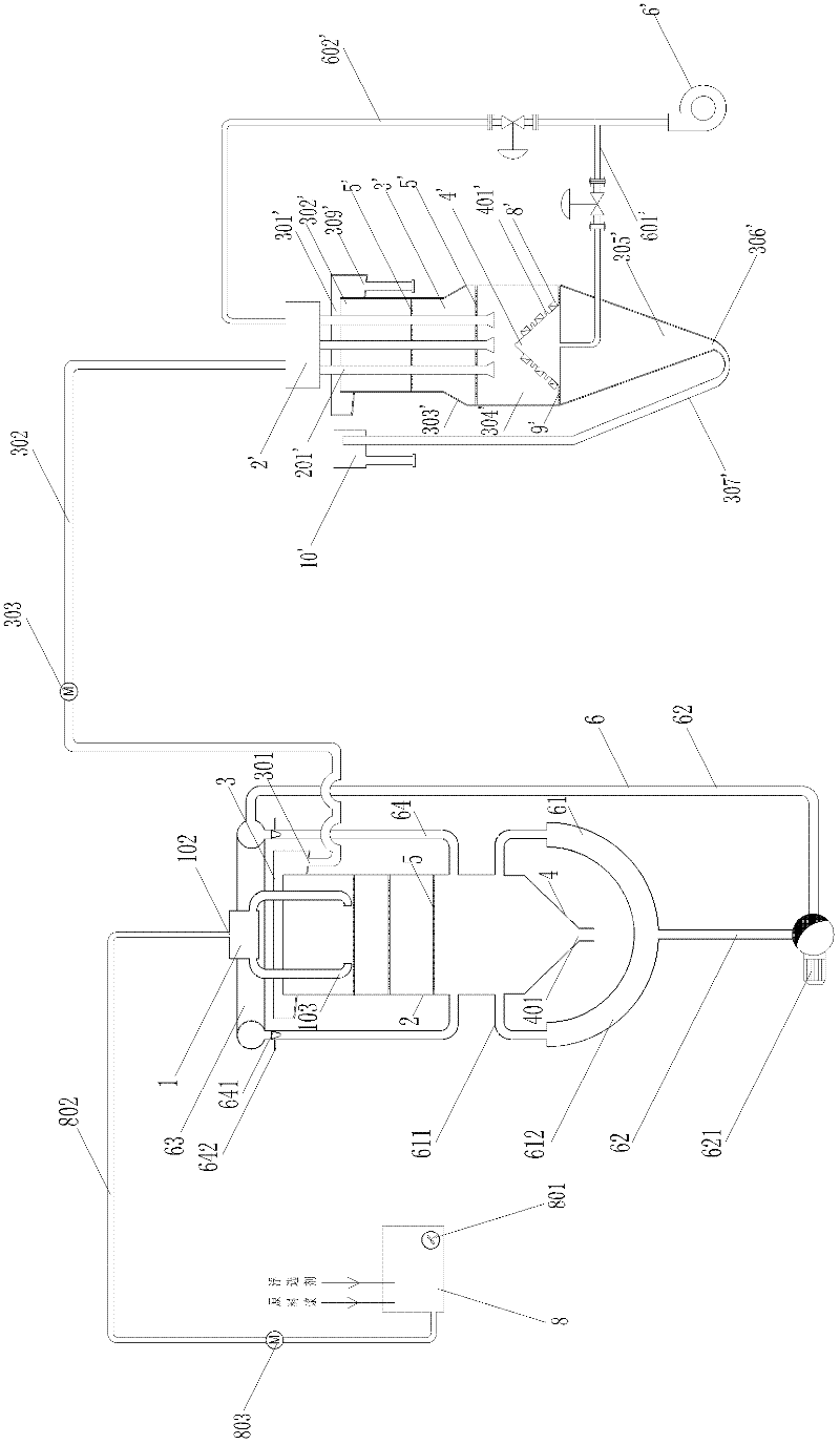
[0076] Such as image 3 As shown, embodiment 2 of the present invention is similar to embodiment 1, and its difference is: 1, the first flotation separation device is not provided with tail ash pipeline 402, liquid level regulating device, tail ash box 7; 2, the second In the flotation separation device, the tail ash outlet 306' is connected to the tail ash pipeline 307', and the end of the tail ash pipeline 307' is provided with a tail ash box 10' and a liquid level adjustment device, where the tail ash pipeline, the liquid level adjustment device, the tail ash The structure and connection relationship of the gray box are the same as before, and will not be repeated here.

Embodiment 3

[0078] Such as Figure 4 As shown, embodiment 3 of the present invention is similar to embodiment 2, and its difference is: the second flotation separation device also comprises stocker 1 ', and the discharge pipeline 302 of the first flotation separation device leads to this storage Material device 1'. Stirring device 101' is arranged in material storage device 1', and feeding pipeline 102' is arranged at the lower part of material storage device 1', and slurry pump 103' is arranged on feeding pipeline 102', and the feeding pipeline 102' leads to distribution device 2 '.


PUM


Abstract

The invention discloses a self-gas supply mixed fly ash multistage flotation separation system, which comprises at least two flotation separation devices, wherein the first flotation separation device comprises a circulating device and the second flotation separation device comprises a gas diffusing device; a circulating tube has a Venturi tube structure, and a gas supplementing device is arranged at a position, which corresponds to the Venturi tube structure and where a negative pressure is formed, on the side wall of the circulating tube; the surface of the gas diffusing device has a plurality of air holes which form different angles with a horizontal plane respectively; and the discharging hole of the first flotation separation device is communicated with a distribution device of the second flotation separation device through a discharge tube. The system has the advantages that: 1, the self gas supply is realized by using the Venturi tube structure; and 2, the floating in a disturbed flow state of air bubbles in a cylinder is realized by using the conical gas diffusing device, so a better flotation effect is achieved.

Description

technical field [0001] The invention relates to the production of activated carbon by using fly ash, more specifically, the invention relates to a self-gas supply mixed fly ash multistage flotation separation system. Background technique [0002] Fly ash is one of the largest industrial wastes in my country, and the annual slag discharge in China has reached 30 million tons at this stage. With the development of the power industry, the discharge of fly ash from coal-fired power plants is increasing year by year. Fly ash contains a large amount of unburned carbon particles, which can be used as a raw material for the manufacture of activated carbon after flotation. [0003] Chinese patent 200810031474.7 discloses a special flotation column for fly ash. A slurry distributor is installed on the top of the flotation column cylinder. There are multi-section bubbling plates inside the cylinder. Multi-point swirl devices and multi-point tail ash are installed at the bottom of the ...

Claims


Application Information

Patent Timeline
Patent Type & Authority Applications(China)
IPC IPC(8): B03D1/14
Inventor 许闽清
Owner FUJIAN LONGYAN LONGNENG FRYASH COMPREHENSIVE UTILIZATION
Learn More