Heat exchanger structure and isothermal compression or expansion chamber

A technology of expansion cavity and heat engine, applied in the direction of moving duct heat exchanger, heat exchange equipment, indirect heat exchanger, etc., can solve the difference of heat exchange temperature, can not realize isothermal compression and expansion, low heat pump cycle efficiency, etc. question

Inactive Publication Date: 2011-11-16
思迪莱尔(简易有限公司)
View PDF5 Cites 4 Cited by
  • Summary
  • Abstract
  • Description
  • Claims
  • Application Information

AI Technical Summary

Problems solved by technology

The problem with current Stirling engines is that when said Stirling engines have good engine cycle efficiency they will have low heat pump cycle efficiency and vice versa
[0013] The reversible use of these engines or the inefficiency of their use over a wide operating range stems from the different losses that occur in them, and especially from temperature differences in the heat exchange
Another cause of irreversible losses in a Stirling engine, or in any engine that theoretically implements isothermal compression and expansion, is that real systems are far from being able to achieve such isothermal compression and expansion

Method used


Image

  • Heat exchanger structure and isothermal compression or expansion chamber
  • Heat exchanger structure and isothermal compression or expansion chamber
  • Heat exchanger structure and isothermal compression or expansion chamber

Examples


Embodiment Construction

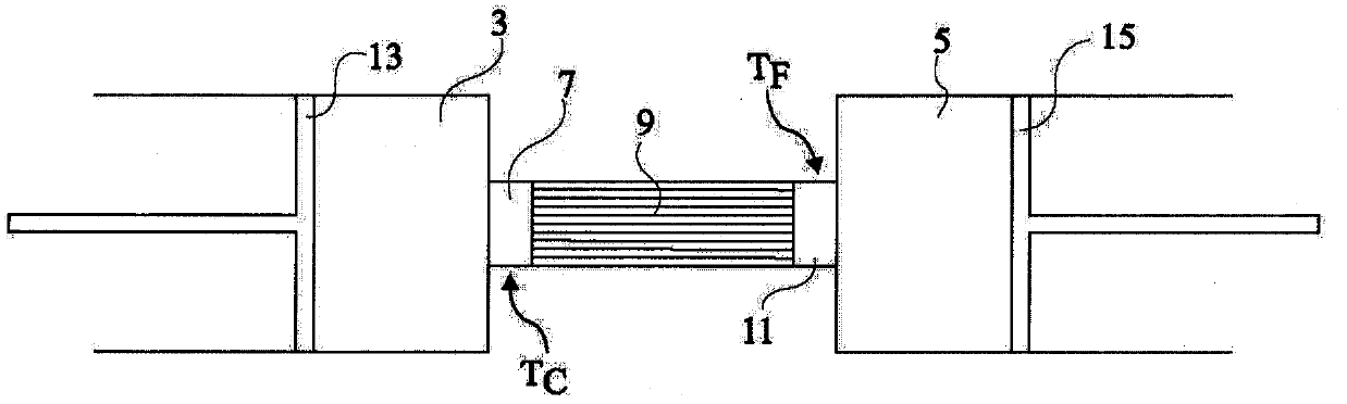
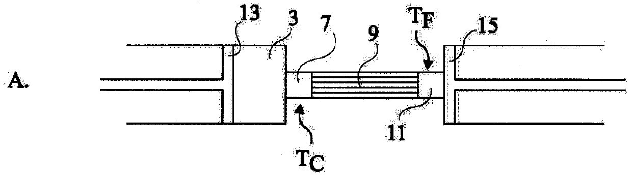
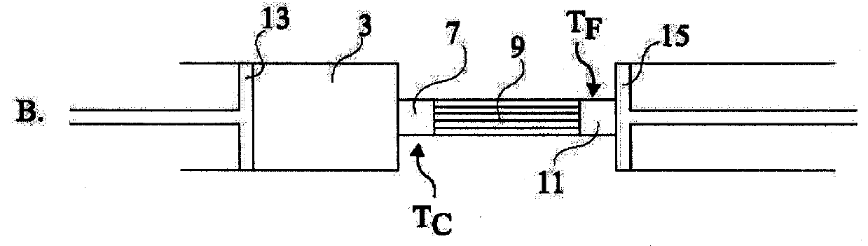
[0041] Embodiments of the present invention first provide for placing the heat exchanger directly in the compression and expansion chambers. It further provides formed compression and expansion chambers in which said exchanger comprises a number of parts forming partitions in said chambers. Such partitions extend from two opposing walls of the chamber and are staggered as the volume of the chamber decreases.

[0042] Figure 3A to Figure 3C The compression chamber or expansion chamber is shown in longitudinal section, as described above, forming part of, for example, a Stirling engine. These figures show different states in isothermal expansion.

[0043] exist Figure 3AIn the cylinder, a chamber 21 is formed in the cylinder and delimited by two walls 23 and 25 that are movable relative to each other in the cylinder. The example shown assumes a movable wall 23 associated with a piston shaft 27 and a fixed wall 25 fixed relative to a heat accumulator 29 (not detailed). It ...


PUM


Abstract

The invention relates to a thermodynamic machine that includes at least one chamber (21) in which an isothermal expansion and / or compression is to be carried out, said chamber being longitudinally defined by first and second walls (23, 25) that are mobile relative to each other. The chamber (21) is divided by partitions (31, 33) extending longitudinally from each of the first and second walls, the partitions being interleaved within each other, and the distance between the partitions extending from a same wall being such that the ratio between the distance squared and the cycle duration of the thermodynamic machine is lower than the average thermal diffusivity of the gas contained in the chamber.

Description

technical field [0001] The present invention generally relates to a heat exchanger structure. The invention also relates to cavities in which isothermal compression and / or expansion takes place. The invention further relates to a highly efficient reversible heat engine comprising such a cavity, eg a Stirling engine. Background technique [0002] Stirling engines are sometimes used in industrial refrigeration and in military or space applications. Such an engine has the advantage that it can be used as an engine or to generate heat or cooling without the use of refrigerants, which are often polluting. Another advantage of the Stirling engine is that its heat source is external and thus can be obtained by any known fuel type or even by solar radiation. [0003] In the Stirling cycle, a gas, such as air, hydrogen, or helium, undergoes a four-stage cycle: isothermal heating, isothermal expansion, isothermal cooling, and isothermal compression. [0004] figure 1 is a generic...

Claims


Application Information

Patent Timeline
Patent Type & Authority Applications(China)
IPC IPC(8): F02G1/053F02G1/055
CPCF02G1/055F02F3/28F28F21/04F02G1/053F28D11/06F02G2256/02F02G2255/20
Inventor 皮埃尔·沙拉
Owner 思迪莱尔(简易有限公司)
Why Eureka
Try Eureka